
Figure 1.
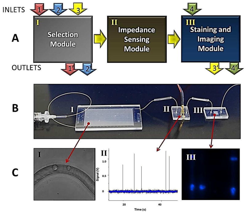
Modular microfluidic system for CTC analysis. (A) Schematic representation of the operation of the system and the three modules comprising the system including the HT-CTC module, the impedance sensing module and the staining and imaging module. Arrows indicate flow of sample (1 and 1′), wash buffer (2 and 2′), CTC release buffer (3 and 3′), and fixation and staining reagents (4 and 4′). For detailed operational procedures please refer to the Experimental section. (B) Picture of the assembled system. Roman numerals correspond to modules described in (A). (C) Micrographs and data plots showing various outputs of the three modules including: (I) HT-CTC selection module for the positive selection of CTCs; (II) electrical signatures of CTCs obtained using the impedance sensor module; and (III) images of CTCs stained with DAPI and collected at the staining and imaging module.