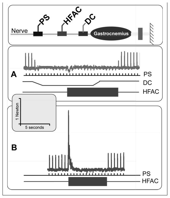
Figure 5.
DC+KHFAC no-onset blocking system. Diagram shows schematic electrode configuration on the nerve, with a proximal stimulating electrode (PS), a KHFAC electrode, and a distal direct current (DC) electrode. “A” shows the no-onset block. Top trace shows tendon tension during trial. Proximal stimulation (PS) at 2 Hz is delivered throughout the trial (middle trace). DC (middle trace) ramps down (cathodic block) and plateaus at 4.5s, producing complete block (note partial block during ramp). DC block allows KHFAC (lowest trace) to be turned on without producing an onset response (7.5s). DC is turned off and block is maintained by KHFAC. KHFAC is turned off at 17.5s and normal conduction is restored. “B” shows the normal KHFAC onset (when DC block is not used). Scale is the same for both graphs.

