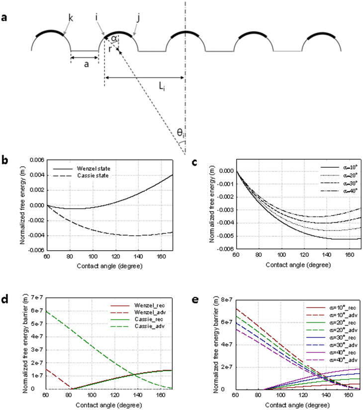
Figure 5. Contact angle analyses of the nanolens array.
(a), Schematic illustration of the nanolens array structure for theoretical calculation. The bold line indicates the contact between the nanolens and a liquid droplet. The resulting contact angle is obtained through thermodynamic analysis. In addition, advancing (i → k) and receding (i → j) cases are taken into account to obtain the lowest surface energy. (b), Normalized free energy (FE) versus contact angle. The composite (Cassie) and noncomposite (Wenzel) wetting states are considered in the calculation. The Wenzel and Cassie states show the minimum free energies at angles of 82° and 138°, respectively. (c), Normalized free energy of the nanolens array. The normalized FE decreases with increasing the arc angle of the nanolens. (d), Normalized receding and advancing free energy barrier (FEM) versus contact angle. The Cassie state has much bigger CAH than the Wenzel state. (e), Normalized free energy barrier (FEM) analyzed according to the arc angle.

