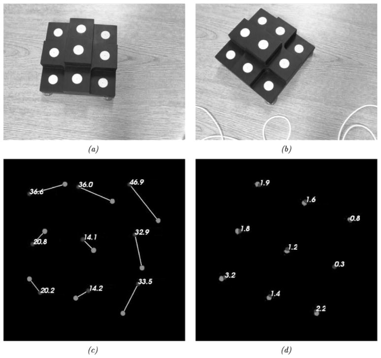
Fig. 10.
Example perspective STE and results. The top row shows the initial and serial positions of the phantom and scanning FOV. The bottom row shows the initial shift vectors and the error vectors for the shift calculated via shift-tracking protocol. (a) Initial position. (b) Camera pose and phantom position change. (c) Induced shift vectors observed via optical tracking system. (d) STE vectors produced from shift-tracking protocol.

