FIGURE 1.

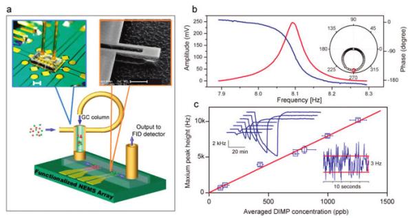
Experimental setup and NEMS resonator gas sensing performance. (a) Schematic view of an array of NEMS resonators encapsulated in a micromachined flow channel, connected with a GC column (parts are not drawn to scale). The channel total volume is 15 nL. Left inset: photo of an actual assembly of the system. Scale bar: 1 mm. Right inset: Scanning electron micrograph of a cantilever NEMS resonator with an integrated piezoresistive transducer having dimensions of length, 2.5 μm; width, 0.8 μm; and thickness, 0.13 μm. Scale bar: 1 μm. (b) Amplitude (red) and phase (blue) resonant response of the cantilever at atmospheric pressure, displaying a quality factor of 200. Inset: polar plot of the same resonant response, where the axial axis is amplitude, and the radial axis is phase. The red marker shows the phase-locking point at the maximum response amplitude. (c) Time-dependent response of a polymer-coated NEMS resonator to varying concentrations of DIMP. Upper inset: chromatogram peaks obtained at various DIMP concentrations using a 10 m column. Lower inset: short-term frequency fluctuations of the NEMS resonator showing a rms amplitude of 1.5 Hz. At a signal-to-noise ratio of 3:1, this corresponds to a limit of detection for DIMP at equilibrium of 0.6 parts per billion.
