Figure 5.

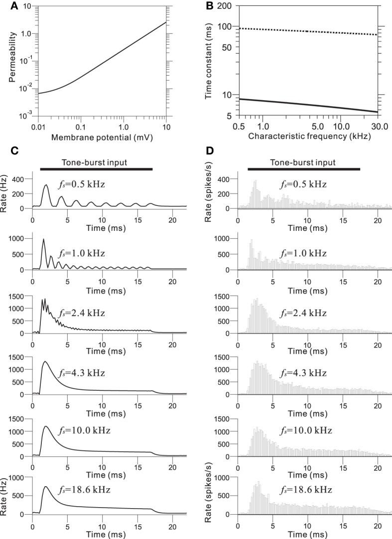
(A) Transmitter permeability as a function of membrane potential in the model of the AN fiber. (B) Two time constants of the AN fiber model as a function of the CF of the fiber. (C) Output waveforms of the IHC-AN synapse model. The LRF (fs) of the piezoelectric membrane where each model IHC-AN synapse was located is indicated on the upper left of the corresponding trace of the model waveforms. (D) PSTHs based on 500 trials and a 0.2-ms bin size. The LRF (fs) of the piezoelectric membrane where each model AN fiber was located is indicated on the upper left of the corresponding trace of the model waveforms.
