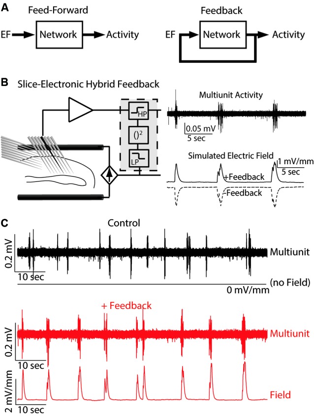
Figure 1.

Hybrid biological-electrical system. (A) Control diagrams for both feed-forward and feedback application of EF stimulation. (B) Left: Schematic of the system where EF is applied based on the ongoing neuronal activity. Right: Example multiunit trace of typical endogenous activity (top) and the simulated EF applied for both positive and negative feedback. (C) Multiunit activity and applied EF for both control (top, black) and positive feedback (bottom, red). Reprinted with permission (Frohlich and McCormick, 2010).
