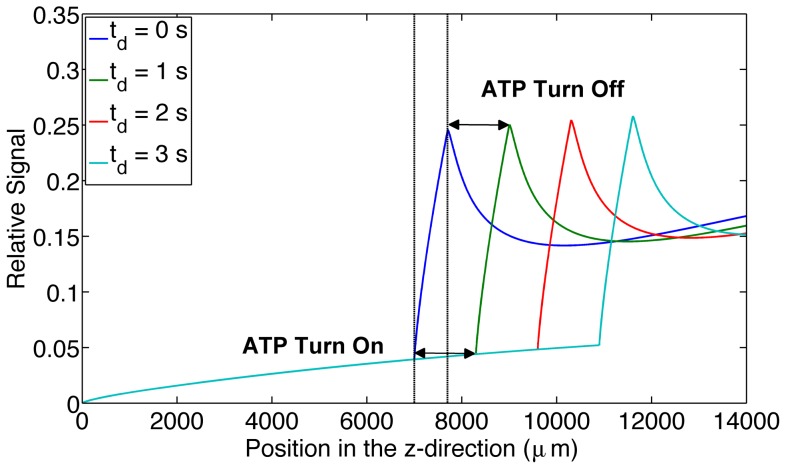
Figure 4. Shows the effect of increasing ATP release times.
The figure displays the relative output signal for increasing ATP release times (0 s, 1 s, 2 s and 3 s) as a function of longitudinal position (µm) throughout the microfluidic device. ATP release turn on and turn off time is indicated on the graph for the 1 s delay time.

