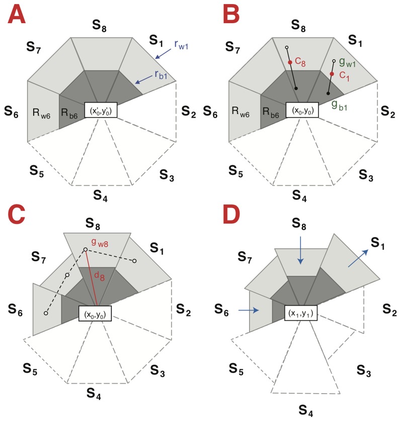
Figure 1. Illustration of the mean-shift model.
A. Initialization of the generic kernel based on the user-defined position (x’0,y’0).
The kernel (here an octagon, ndir = 8) is divided into sectors (S1 to S8), each one containing two nested triangle-shaped regions (Rb and Rw), one sensitive to dark and the other to bright pixels (“b” means “black” and “w” means “white”). Here, Rb6 and Rw6 are shown, with a total of 16 regions (Rb1 to Rb8 and Rw1 to Rw8). Only the contours of sectors 2-5 are shown in order to lighten and better visualize the figure. The cell is not presented for clarity.
B. Adjustment of the position of the center at t0.
Sixteen mass centers (gb1 to gb8 and gw1 to gw8) are first calculated from the intensities of the pixels from each region, (gb1 and gw1 are shown). Sector mass centers (C) are calculated from gwn and gbn, (C8 is shown as an example). The center (x0,y0) is defined as the centroid of the mass centers C1 to C8.
C. Adaptation of the kernels to cell morphology at t0.
The distances (di) between each mass center (gwn) and kernel center (x0,y0) are calculated (d8 is shown as an example). The new outer radii (rwn) are calculated based on dn, the average dn distances, the expansion factor and the anisotropy factor. rbn is assigned according to the ratio (rb / rw), which is initially defined by the user.
D. Representation of the kernels at t1.
Information is obtained applying the processes explained in B and C. The size of the sectors will increase or decrease (indicated by the arrows) as a function of cell shape modifications.

