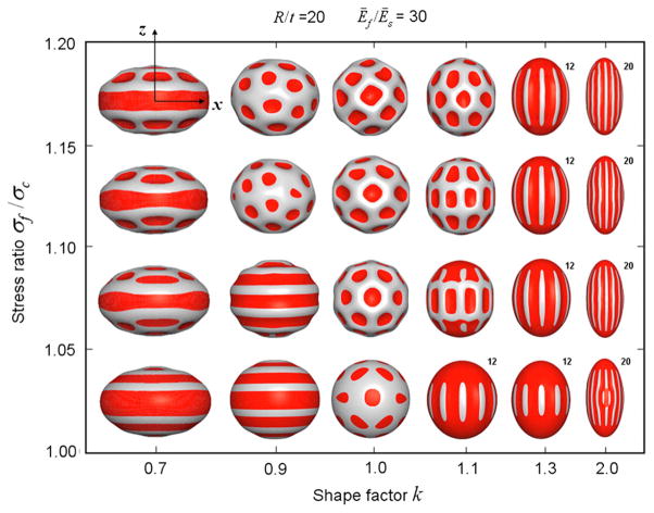
Fig. 9.
Buckling deformation maps of stiff-shelled spheroids with equatorial radius α, polar radius b, and shell thickness t, from Yin et al. (2008). The radius of curvature at the pole is R=a2/b and the shape factor k=a/b. Deformations of the outer shell are shown as shape factor k and ratio of stress in the film (shell) to critical buckling stress (σf/σc) are varied. The radius/thickness ratio R/t =20 and the modulus ratio between film and substrate Ef/Es = 30 are both held constant. The amplitude of the mode in each image is arbitrary; the color red indicates relatively concave regions. Reproduced with permission from Yin et al. (2008). (For interpretation of the references to color in this figure legend, the reader is referred to the web version of this article.)

