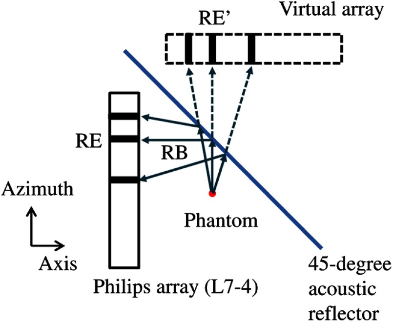
Fig. 1.
Top view of the experimental setup. RB, reflected beam; RE, physical receiving element; RE’, virtual receiving element. The commercial Philips array operated in B-mode to collect photoacoustic signals, a 45-deg acoustic reflector (glass) formed a virtual array, and a laser illuminated light orthogonally to the drawing from the top (not shown in the figure).

