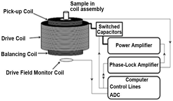
Scheme 1.

Diagram of the apparatus used to measure the MSB signal from mNP samples. A sinusoidal voltage of a given frequency and amplitude are generated by phase-lock amplifier controlled by computer. This voltage is output to the power amplifier, which drives the current into the resonant drive coil. The computer switches the capacitor to create variant resonant frequency of the drive coil. The output voltage of the phase-lock amplifier is adjusted by monitoring the current generated in a field measurement coil to obtain the correct drive field. The pickup coil and balancing coil were fixed inside the drive field coil in series. The output is measured by the phase-lock amplifier, which output the measured voltage in pickup coil at each harmonic to the computer.
