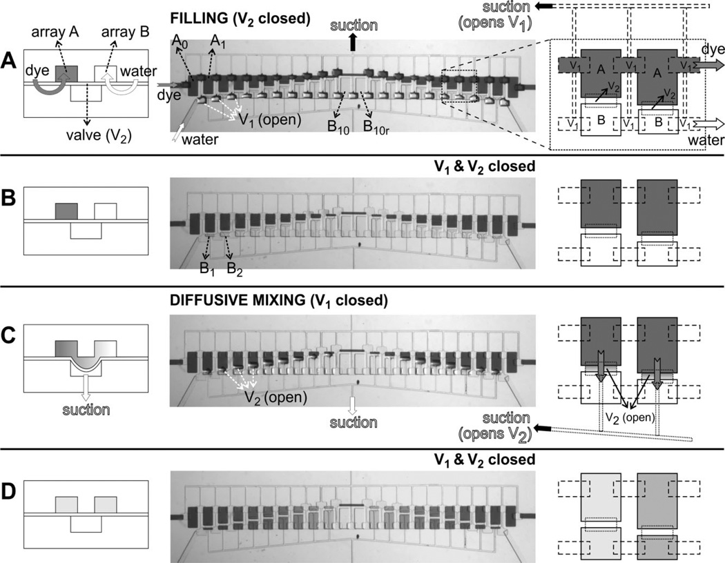
Figure 2.
Device operation. Operation of the device consists of four steps (A–D) shown in cross-sectional schematics (left column), top-view optical micrographs (middle column), and top-view schematics (right column). Left schematics correspond to a line orthogonal to both arrays and the right-column schematics correspond to an area comprising 2 × 2 microchambers, as indicated by the dashed-line square in the top-view optical micrograph in (A). For clarity, the pneumatic lines are shown only when suction is applied. (A) Initial filling of microchambers. Suction is applied to the top pneumatic lines (black arrow) in order to open valve set {V1} while valve set {V2} is kept closed; then array A is filled with colored dye (dark gray fluid, dark gray arrows) and array B is filled with de-ionized water (white arrows). Note the curvature of the {V1} membranes in the optical micrograph. (B) Isolation of each fluidic chamber after {V1} is closed. (C) Diffusive mixing between each A–B pairs after suction is applied to the bottom pneumatic lines (which open valve set {V2}). Note the gradient forming in the fluidic connection after mixing starts. (D) State of the device at the end of a mixing experiment (after closing valve set {V2}) where a sequence of 11 dilutions, one on each pair of isolated microchambers, is created due to differences in microchamber volumes between arrays A and B; the right-column schematics depict two of these 11 dilutions (dark and light shades of gray).

