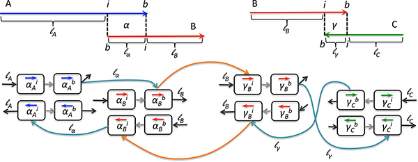
Figure 2.

Extension graph for two terminal alignments. Terminal alignments α between contigs A, B and γ between B, C are each represented by eight nodes. Nodes encode the extremities of the alignment on each contig (border b and internal i extremities) and the direction in which it is read (forward → or reverse ←). Edges encode the possible "glue" between contigs. Light gray edges represent a given alignment on the contig and carry no weight. Turquoise edges connect two contigs within an alignment and are labeled by its length ( lα and lγ ). Black edges connect to the In and Out nodes, allowing for reading each contig in both directions as well as complex paths and are labeled by the remaining contig length (lA, lB and lC). Notice that values of lB on the left-hand side of the figure and on the right-hand side are not the same as they depend on the alignment length; they are |B| − lα and |B| − lγ, respectively. Orange edges connect the extremities of different alignments in which one contig can participate: here α and γ for B. Their weights are deduced from the corresponding intervals (here |B| − lα − lγ for both).
