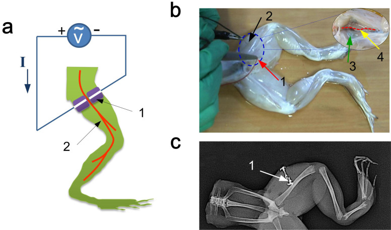
Figure 7. Nerve electrical stimulations based on the injectable electrode.
(a) Schematic of in vivo experimental setup for loading the electrical stimulations to the sciatic nerve of a frog; here symbols 1, 2 denote the fabricated electrode and sciatic nerve, respectively; (b) Illustration for the electrical stimulation to the frog's sciatic nerve; the inset is the topography of the frog's tissue with sciatic nerve and injectable electrode; here symbols 1 and 2 are respectively the positive and negative leads of the electrical input signal, symbols 3 and 4 respectively denote the injectable electrode and sciatic nerve. (c) X-ray image of the injectable electrode inside the targeted tissue of the frog's leg; symbol 1 represents the injectable electrode.

