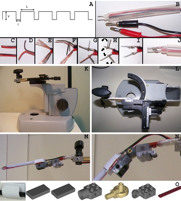
Figure 2. Description of electrode and manipulator building process. A, Electroporator pulse variable parameters: V: pulse voltage value; I: interval between pulses; L: pulse length. B, Completed electrode with the platinum poles and the connector plugs. C, Both ends of the copper speaker cables must have a clean cut. D, Separation of the positive and negative cables at a single end. E, The positive and negative cables were stripped for 1 cm revealing the naked copper wire. F, Insertion of a platinum rod into the midsection of the negative pole's twisted copper wire. G, Insertion of the second platinum rod into the positive pole. H, Both copper wires were further twisted and bent over to secure the platinum rods and to increase contact surface. I, The contact between the platinum rods and copper wires was further stabilized by adding a drop of solder to the interface. J, The wires were threaded through an empty ball point pen cartridge, which acts as the solid outer shell of the electrode. K, Lateral view of the microscope base with the modified slide holder mechanical stage attached at the top. L, Top view of the adapted microscope base with emphasis on the mechanical stage. Note that the slide holder attachment was removed and substituted for a screw (arrow) that secures the arm of the LEGO electrode holder (M). N, Detailed view of the electrode holder hinge. O, Components that comprise the electrode holder hinge. The LEGO parts can be acquired separately through the LEGO website or are included in the 4507 set. The wire holder (available through 3M, Brazil) was glued to the top of the flat pieces and the electrode outer shell was inserted in the wire holder.

