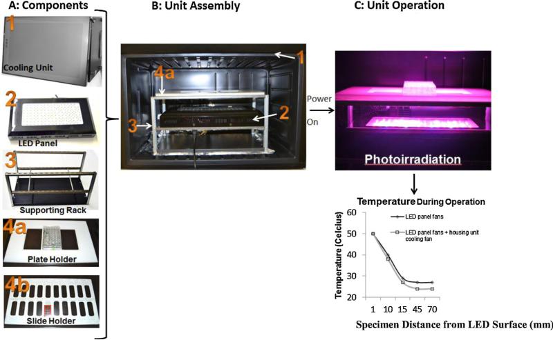
Fig. 1.
Assembly and operation of the LED array device. (A) The components include: (1) a cooling housing unit, (2) an LED array panel, (3) aluminum supporting stand, (4a) plate holder, and (4b) slide holder. (B) LED array device assembly with components inside as numbered in (A). (C) Illustration of LED array device operation and corresponding temperature output measured at tissue-to-air interface with and without cooling. The height of the specimen holder rack can be adjusted to vary the distance from the LED panel surface. Plot showed slightly lower temperature at the tissue-to-air interface with additional cooling from the housing unit.

