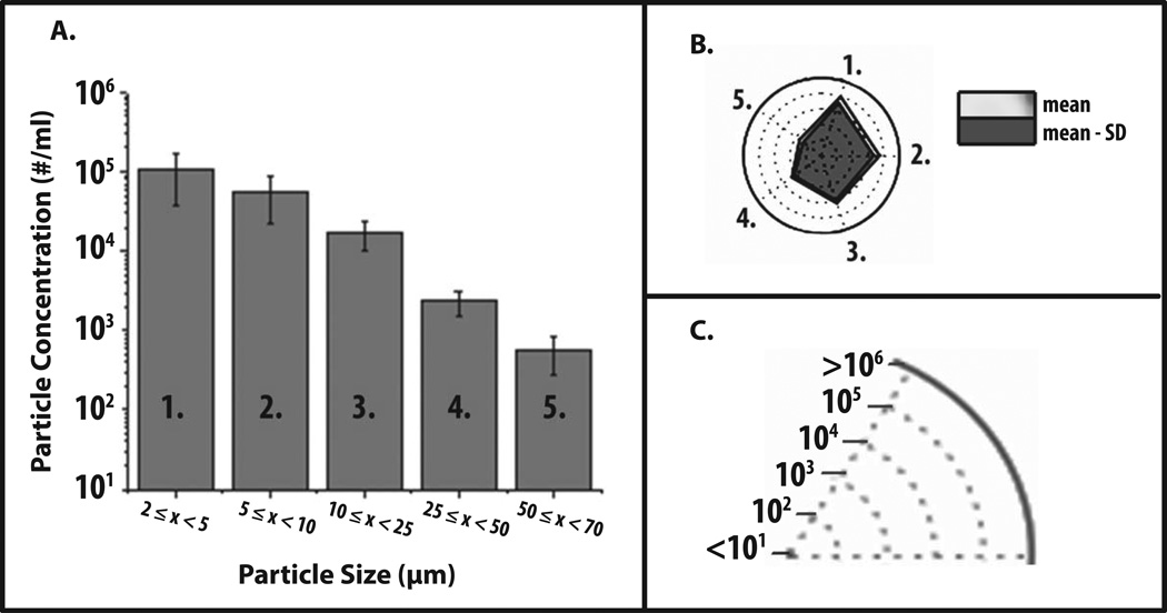
Figure 1. Application of radar chart array analysis to evaluate subvisible particle concentration and size distribution data measured by MFI.
(a) Histogram (n=3) of representative MFI data plotting particle concentration versus particle size (ECD) for an IgG1 mAb solution containing 20 mM citrate-phosphate buffer at pH 8.0 and 1 M NaCl subjected to 4 hours of shaking. (b) Radar chart presentation of the same data set; each axis is labeled with a number and is the same size range as the corresponding numbered bin size in the histogram. The values along the each axis of the radar chart are connected linearly to visualize the data set as a polygon. The perimeter of the outermost polygon represents the mean particle concentration, the polygon labeled ‘mean - SD’ represents the mean minus one standard deviation, and the distance between the perimeters of the two polygons (along an axis) is equivalent to the lower error bar in the equivalent bin of the histogram (one standard deviation). (c) Illustration of the particle concentration (log scale) used in the radar charts in this work to display experimentally measured micro flow imaging subvisible particle concentrations.

