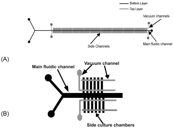
Figure 1.
(A) Schematic representation of microfluidic device to create the chemical gradient. Gray lines indicate control channels in the top layer. Black lines represent fluidic channels in the bottom layer. There are 128 repeat side channel units. (B) Enlarged image of a portion of the chip (not all culture chambers are shown).

