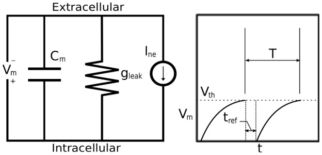
Figure 5. Diagram for leaky integrate-and-fire model.

The circuit diagram (left) represents the schematic layout of the integrate-and-fire components. The graph (right) depicts voltage vs time for a neuron stimulated by a constant current.

The circuit diagram (left) represents the schematic layout of the integrate-and-fire components. The graph (right) depicts voltage vs time for a neuron stimulated by a constant current.