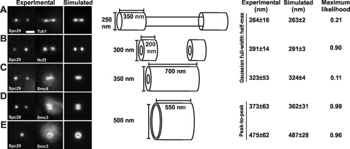
FIGURE 1:
The geometry of spindle components. (A) Experimental images of spindle microtubules (Tub1-GFP) were compared with simulations. Modeled spindle microtubules measured 1.5 μm in length, with two bundles of kinetochore microtubules 350 nm in length and 250 nm in diameter and interpolar microtubules spanning the interkinetochore distance (800 nm) and 130 nm in diameter (Winey et al., 1995; Gardner et al., 2008). (B) Experimental images of kinetochore clusters (Nuf2-GFP) were compared with simulations. The plus ends of the kinetochore microtubules were simulated as hollow cylinders 300 nm in outer diameter. (C) Pericentric condensin (Smc4-GFP) is best modeled as a hollow cylinder with an outer diameter of 350 nm and spanning the length of the pericentric chromatin. (D and E) Pericentric cohesin (Smc3-GFP) is best modeled as a hollow cylinder with a 500-nm mean diameter with a depicted thickness of 50 nm. The radial distance between cylinders containing cohesin and condensin is ∼75 nm. Tables 1 and 3 display values that determine best fit.

