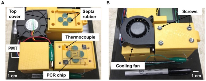
Figure 2. Photographs of the compact fluorescence detector housing assembly for real-time detection of amplified DNA samples.

(A) A PCR chip with a thermocouple placed on top of the optical detector housing (bottom part of the image) and a cover integrated with a cooling fan and having septa rubbers to seal the inlet and outlet of the PCR chip (top part of the image). This cover also completely encloses the PCR chip to prevent ambient light from affecting the reading of the PMT. (B) The fully assembled housing that encloses the PCR microchip. The cooling fan can be seen on top of the housing, as well as screws that provide the tight seal.
