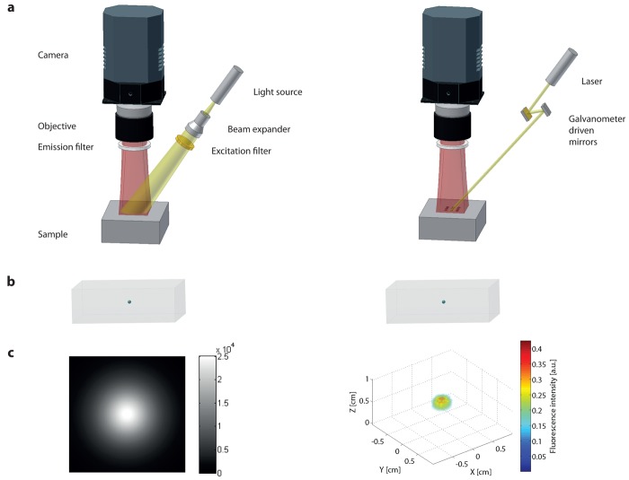
Figure 3.
Planar and FMT imaging: (a), Setup. Schematic of a planar (left) and an FMT (right) measurement setup and its components in reflection geometry. Transmission geometry (not shown) can be easily achieved by installing either the camera or the source on the other side of the sample. (b), Schematic of an embedded fluorophore (turquoise) in depth of a cubic sample (gray). (c), (left) Imaging result of the planar setup showing the light distribution at the surface of the sample. Only qualitative information is obtained. (right) Reconstructed fluorophore of an FMT data set allowing the depth resolution and therefore quantification.

