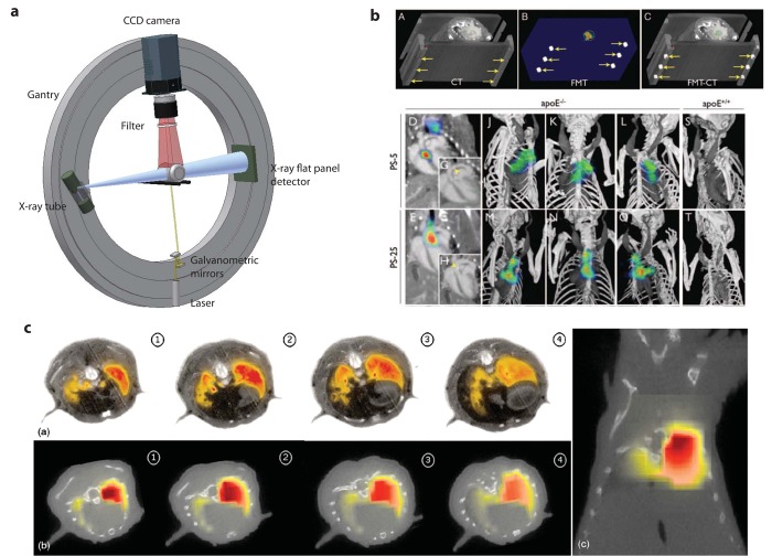
Figure 4.
Applications: (a), Schematic of a hybrid FMT/CT system. Perpendicular to the X-ray tube and flat panel detector axis the FMT instrumentation is mounted consisting of a laser source, a scanning device and a CCD camera. All components are mounted on a rotating gantry holding the sample in its center.(b), Sequential FMT/CT example of artherosclerotic plaques in mice. A through C, Image co-registration is based on fiducial landmarks (arrows) that are incorporated into the animal holder and are identifiable on CT (A) and FMT (B). The software co-aligns these fiducial markers to created a hybrid data set (C). Fluorescence signal in the aortic root of an apoE−/− mouse is encircled. D and E, 2-dimensional FMT/CT long axis views of apoE−/− mice injected with respective protease sensors. Fluorescence signal is observed in the aortic root and arch, regions with high plaque load. G and H, CT only views of D and E. Arrow heads depict vascular calcification, likely colocalizing with plaques. J through O, 3-dimensional maximum intensity projection of hybrid data sets show skeletal and vascular anatomy and the distribution of fluorescence signal. Most signal is observed in the root and arch. S and T, FMT/CT after injection of respective sensor into wild-type mice (Adapted from [76]; reprinted with permission). (c), Hybrid imaging example of a lung inflammation mouse model. (a) Cryoslice images overlaid with normalized fluorescence image; reconstruction using weighted segments regularization (b) transversal slices and (c) coronal slice (Adapted from [82]; reprinted with permission).

