Figure 5.

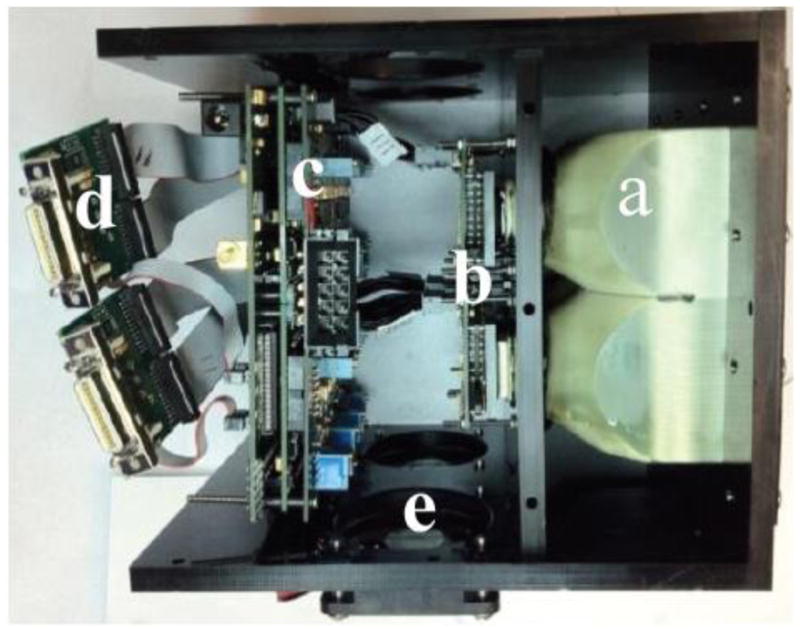
Side view of complete assembly of 2×2 array. a) 2×2 fused taper assembly. b) 2×2 array of sensors mounted on individual headboards. c) Circuit boards to drive the sensors. d) CameraLink output e)Cooling assembly

Side view of complete assembly of 2×2 array. a) 2×2 fused taper assembly. b) 2×2 array of sensors mounted on individual headboards. c) Circuit boards to drive the sensors. d) CameraLink output e)Cooling assembly