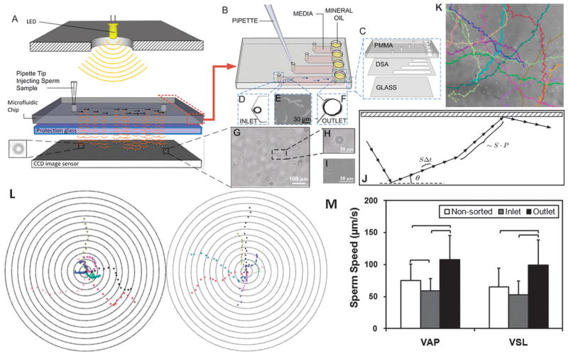
Fig. 8.
Sperm sorting. (A) Lensless imaging platform (LUCAS) integrated with a microchip for sperm tracking as highlighted by Nature Photonics.239 Shadows of the sperm generated by diffraction can be imaged using CCD in one second. (B) Loading sperm samples into microchannels of the space-constrained microfluidic sorting (SCMS) system from the inlets. The SCMS system with different channel lengths is assessed for effective sperm sorting. (C) The chip has three layers: PMMA, double-sided adhesive film (DSA), and glass coverslip. (D) Image of the channel inlet with a diameter of 0.65 mm under a 2×. (E) Image of sperm swimming inside a microchannel under a 10× objective. (F) The channel outlet with 2 mm diameter viewed using a 2× objective. (G–I) Sperm shadows on LUCAS. (J) A schematic of the trajectory of a sperm performing a Persistent Random Walk (PRW), where S is the velocity, P is the persistence time, Δt is the time step, and θ is the angle the trajectory makes with the x-axis. (K) Sperm tracks from image analysis. (L) Bull’s eye plot showing sperm motility vectors in the horizontal (left) and vertical (right) configurations. The distance between the adjacent concentric circles is 100 μm. (M) Comparison of Average Path Velocity (VAP) and Straight Line Velocity (VSL) of sperm for non-sorted conditions, and at the inlet and outlet of the 7 mm long microfluidic channel. The VAP and VSL were observed to be significantly greater for the sperm cells imaged at the outlet of the microfluidic channel compared to non-sorted sperm and the sperm at the inlet. Therefore the microfluidic sperm tracking system presented here shows potential to be also used as a sorting platform (n = 33–66, brackets indicate statistical significance with p < 0.01 between the groups). Reproduced with permission.115

