
Figure 1.
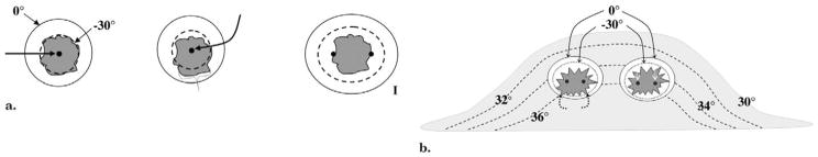
(a) Diagram shows basic isotherms for single and double cryoprobes. Accurate central placement of a single 2.4-mm cryoprobe (left image, arrow) within a simulated 1.2 × 1.2-cm tumor (dark gray) may still not produce sufficient lethal ice to cover all tumor margins (dashed line ~ <−30°C, diameter ~ 1.2 cm). Even though visible ice (solid outer line) may appear to cover all tumor margins, slight off-center placement (middle image, arrow) leaves grossly untreated tumor (bracket) beyond the lethal isotherm (dashed line). Tumor on right is covered by lethal ice due to synergy produced by two cryoprobes (15). (b) Avoiding posterior positive margins: heat load effects of the chest wall. The estimated temperature difference between skin surface (30°C) and chest wall/body (36°C) causes greater heat load along the posterior margin of ice propagation, which narrows the posterior distance between the visible (0°C) and lethal (–30°C) isotherms (curved solid arrows). Ablation on left shows central position of cryoprobes and greater anterior extension of visible ice beyond tumor margin; however, incomplete coverage of posterior tumor margins (black dashed arrows) is noted, similar to that seen in prior series (24–26). Ablation on right shows through tumor coverage by lethal ice due to more posterior placement of cryoprobes in tumor (white straight arrows), thus overcoming heat-sink effect along the chest wall.