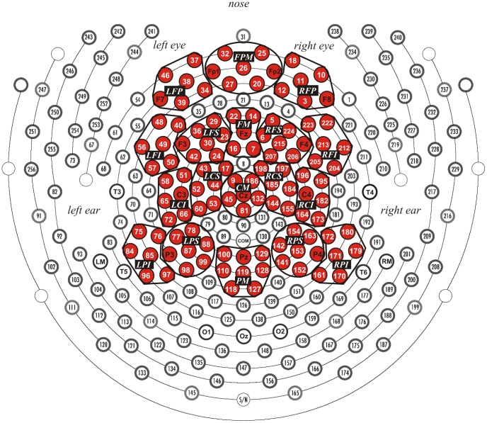
Figure 1. Geodesic sensor net layout.
Electrode sites are numbered. Red clusters are regions of interest included in analyses. LFP = left frontal-polar, FPM = frontal-polar medial, RFP = right frontal-polar, LFI = left frontal inferior, LFS = left frontal superior, FM = frontal medial, RFS = right frontal superior, RFI = right frontal inferior, LCI = left central inferior, LCS = left central superior, CM = central medial, RCS = right central superior, RCI = right central inferior, LPI = left parietal inferior, LPS = left parietal superior, PM = parietal medial, RPS = right parietal superior, RPI = right parietal inferior.

