
Figure 2.
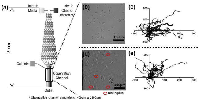
(a) Microfluidic device schematic. Solutions introduced into the two inlets are mixed while traversing the serpentine channels to establish a stable concentration gradient across the observation channel. While a gradient of fMLP is established by introducing media into the inlet 1 and fMLP solution into the inlet 2, a competing gradient of LTB4-fMLP is established by introducing LTB4 solution into the inlet 1 and fMLP solution into the inlet 2. (b) Neutrophils on a fibronectin-coated surface in the observation channel. (c) Trajectories of 20 representative control neutrophils (unactivated) within the fMLP gradient. (d) Neutrophils on an endothelial cell-coated surface in the observation channel. (e) Trajectories of 20 representative control neutrophils (unactivated) within the fMLP gradient.