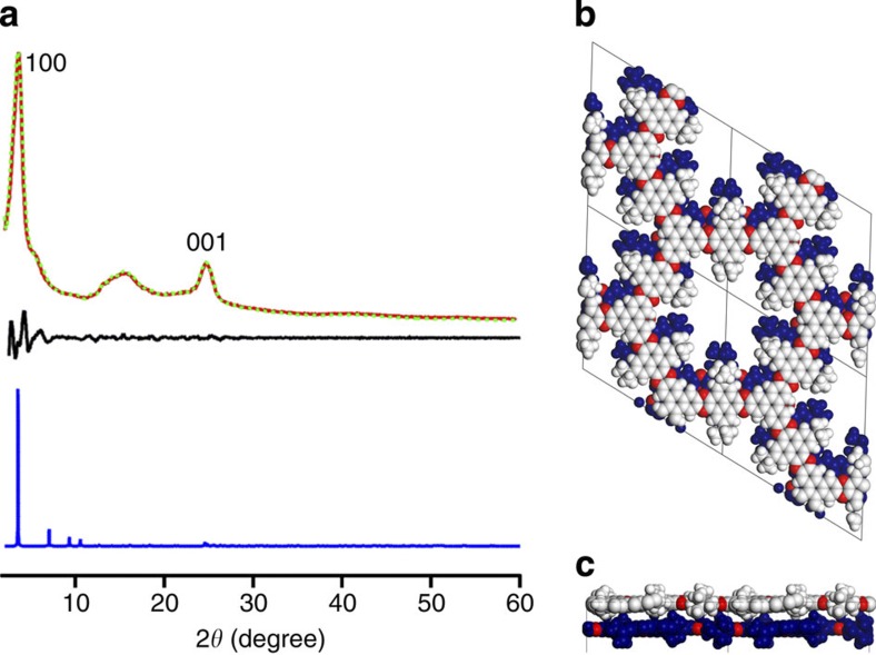
Figure 4. XRD pattern and crystalline structure.
(a) XRD profile of CS-COF (red curve), the Pawley-refined pattern (green curve) and their difference (black curve). XRD patterns were simulated using the P1 space group with the 0.8-Å-slipped AA-stacking mode (blue curve). (b,c) One pore structure of the 0.8-Å-slipped AA-stacking mode along the z- (b) and y- (c) axes.

