
Figure 1.
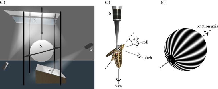
Overview of the experimental set-up. (a) Diagram of the virtual-reality flight simulator. Wide-field visual stimuli were provided by two modified data projectors (1,2) projecting via a system of mirrors (3,4), onto a hollow acrylic sphere coated with rear-projection paint (5). (b) The moth was tethered at the centre of the sphere to a six-component force–moment balance (6). The body axis system shown in the figure (see main text for definitions) was used to resolve the measured forces and moments, and was also used to define the axis of the visual stimulus. The angular velocity components shown here indicate the direction of self-motion of the moth corresponding to a positively signed visual stimulus in roll, pitch or yaw. (c) Diagram of the spherical sinusoidal grating used as a visual stimulus. The rotation axis of the grating was aligned with either the roll, pitch or yaw axis.