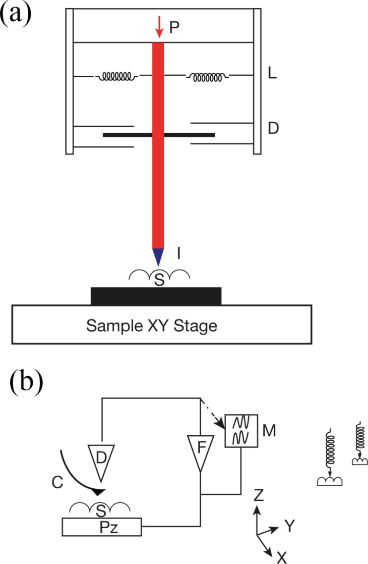
Figure 2.
(a) Schematic of instrumented nanoindenter, including P - calibrated force; L - support springs; D - Position sensor; I - indenter tip supported by shaft; S - sample. (b) Schematic of AFM showing Pz - piezoelectric motion transducer; S -sample; C - integrated cantilever and tip; D - cantilever motion detector; F - feedback; M - monitor for display. To right the working of AFM is shown schematically: extension of spring changes before and after applying load. From [42].

