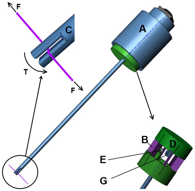
Figure 2. Explanation of the SF sensor components; A-housing, B- spring blades oriented in a circle, C-Close up of tip with fissure, D-hall sensor and magnet.
Due to the force in the thread (F), a torque is created in the tip (T). This torque rotates the shaft in respect of the fixed housing (A). While the spring blades deform, the distance between hall sensor (G) and magnet (E) increases resulting in a change in output signal.

