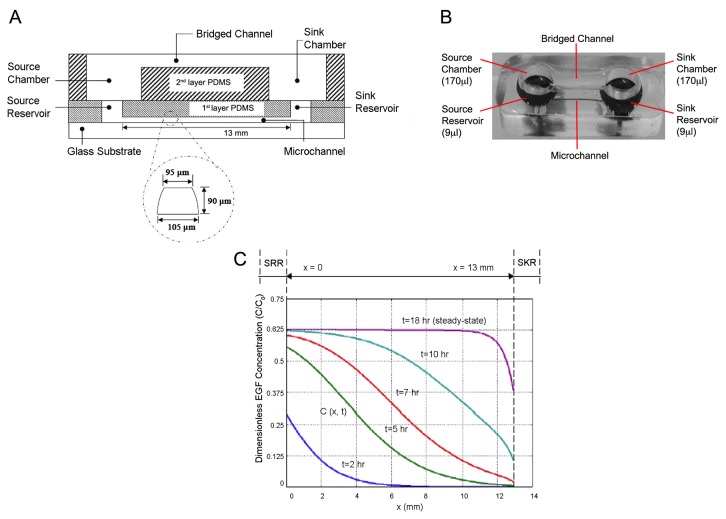
Figure 5. Microfluidic design and modeled gradients of bridged μ-Lane system.
Microfluidic analysis provides precise control over the establishment and maintenance of chemical concentration gradients. Microfluidic function incorporates fluid dynamics, molecular diffusivity over time and hydrostatic fluid balance within all parts of the system. A) The microfluidics design includes a microchannel measuring approximately 13mm (length), 90μm (depth), and 100μm (width), with two reservoirs (source and sink) defined as the first layer PDMS. A second layer of PDMS, the user interface layer, consists of a bridge channel and two chambers (source and sink) bonded on top of the first layer forming a fluidic connection between both layers. B) Double-layer PDMS microfluidic device fabricated after soft lithography and bonding onto glass slides with volume capacities of the chambers and reservoirs indicated. C) Normalized EGF concentrations plotted against increasing distance from the source reservoir (SRR) to the sink reservoir (SKR) as a function of time.

