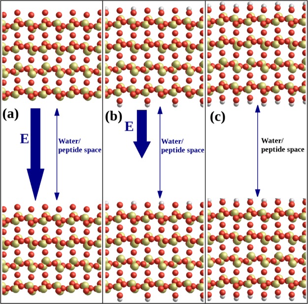
Figure 1.
Illustration of the simulation boxes and crystal structures used in this study; silicon is yellow, oxygen red, and hydrogen gray. (a) The SiO2 surface: the alpha-cristobalite (101̅) surface is cut so that the upper surface is terminated with under-coordinated oxygen, inducing an electric field E across the water/peptide space due to the dipole moment of the crystal slab. (b) The hhSiO2 surface: alternate oxygens on the upper surface are converted to hydroxyl groups, and corresponding hydroxyl groups decorate the lower surface of the slab, reducing the magnitude of the electric field E across the box. (c) The hSiO2 surface: all oxygens on the upper surface converted to hydroxyls with corresponding hydroxyls on the lower surface, so that there is no electric field across the peptide/water space in the simulation box.

