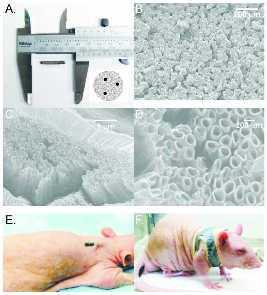
Figure 1.
Implants and implantation method. A: An example of implant used in experiments; the insert shows a diagram of an implant cross-section with 3 thin titanium reinforcing wires. B: Scanning electron micrograph (SEM) of small pore implant without nanotube addition (100x magnification). C: SEM of small pore implant with nanotube addition (20,000x magnification). D: Detailed SEM of nanotube surface structures (50,000x magnification). E: and F: Illustration of implant location and orientation in the back of an anesthetized rat and how implant was secured.

