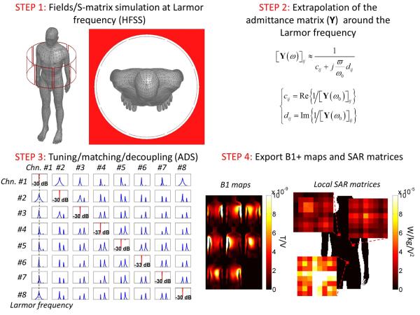
Figure 1.
Flow chart of the co-simulation process for simulation of coupled pTx arrays. In step 2, the admittance matrix Y of the coupled transmit array is extrapolated around the Larmor frequency by assuming that its frequency dependence is purely inductive (cij and dij are the real and imaginary parts of the inverse of the elements of the admittance matrix at the Larmor frequency).

