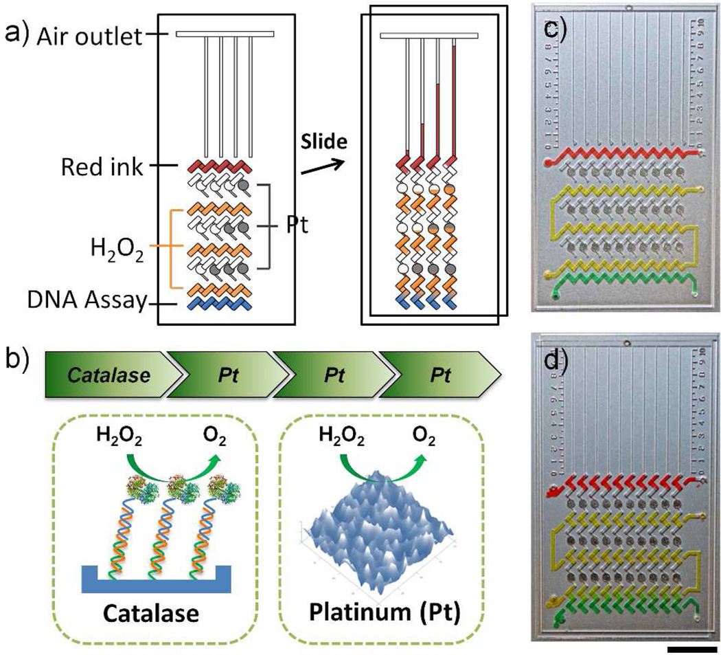
Figure 1.
Working principle of the MV-Chip. (a) Schematic view of a typical MV-Chip for DNA assay. The detection units with platinum amplification (black circles) show larger bar chart advancement than those without amplification. (b) ‘Rocket-like’ propelling mechanism of the MV-Chip. Catalase introduced by DNA hybridization is the initiator and three stages of rough platinum films (Pt) amplify the signals. (c & d) The representative flow path of each reagent before and after an oblique slide: red lane (ink), yellow lane (H2O2), and green lane (DNA assay). Scale bar is 1cm for c) and d).

