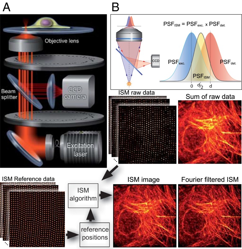
Fig. 1.
Basics of CSD-ISM. (A) Schematic drawing of the optical setup. The excitation light (400 nm, 488 nm, 561 nm, or 647 nm) is coupled into the spin-disk confocal unit via an optical fiber. A Nipkow disk with microlenses focuses the light onto pinholes of an opposing disk. The microscope objective focuses the light emerging from the pinholes to diffraction-limited spots in the sample. The fluorescence emission from these spots is collected by the same objective and passes through the pinholes onto a CCD camera via a dichroic beam splitter. (B) A pixel on the CCD camera, if it is small enough, detects light from a diffraction-limited region of the sample. Pixels offset from the optical axis will detect an area of the sample that does not coincide with the excitation; thus, the product of these two point-spread functions, which is proportional to the amount of light detected, will be shifted. This way, each pixel on the CCD records a confocal image that is shifted by half its distance from the optical axis. The bottom of the figure illustrates the work flow in CSD-ISM. Reference data from a homogenously fluorescing sample is recorded to determine the center position of each pinhole. These reference positions are fed into the ISM algorithm that shifts the raw data from every pinhole, as indicated in B. Finally, Fourier filtering is performed to gain the full resolution enhancement of ISM.

