Abstract
In this research, using direct measurements and Monte Carlo calculations, the potential dose reduction achieved by bismuth shielding in computed tomography was evaluated. The patient dose was measured using an ionisation chamber in a polymethylmethacrylate (PMMA) phantom that had five measurement points at the centre and periphery. Simulations were performed using the MCNPX code. For both the bare and the bismuth-shielded phantom, the differences of dose values between experiment and simulation were within 9 %. The dose reductions due to the bismuth shielding were 1.2–55 % depending on the measurement points, X-ray tube voltage and the type of shielding. The amount of dose reduction was significant for the positions covered by the bismuth shielding (34 − 46 % for head and 41 − 55 % for body phantom on average) and negligible for other peripheral positions. The artefact on the reconstructed images were minimal when the distance between the shielding and the organs was >1 cm, and hence the shielding should be selectively located to protect critical organs such as the eye lens, thyroid and breast. The simulation results using the PMMA phantom was compared with those using a realistically voxelised phantom (KTMAN-2). For eye and breast, the simulation results using the PMMA and KTMAN-2 phantoms were similar with each other, while for thyroid the simulation results were different due to the discrepancy of locations and the sizes of the phantoms. The dose reductions achieved by bismuth and lead shielding were compared with each other and the results showed that the difference of the dose reductions achieved by the two materials was less than 2–3 %.
INTRODUCTION
Since the development of computed tomography (CT) in 1972, the use of routine CT examinations has increased rapidly. Simultaneously, concerns about radiation protection and patient dose have increased in the clinic because of the greater availability of multi-detector CT (MDCT) which provides faster images for larger volumes, but gives large doses to patients. In recent years, MDCT has been reported as an essential diagnostic imaging tool and a main part of diagnostic radiologic examinations. According to the International Commission on Radiological Protection 102, CT studies have increased more than 800 % globally in past decades(1).The increased use of MDCT results in greater individual patient doses and collectively greater doses to the patient population. Therefore, it is prudent and reasonable to explore methods for reducing patient doses in MDCT examinations.
The important protection concept when dealing with patient doses from MDCT is ‘keep as low as reasonably achievable’ (the ALARA principle). Physicians, radiologists, physicists and radiologic technologists must recognise the risks of the patient dose during CT examinations and suggest various and appropriate protocols in order to reduce the dose to radiosensitive organs such as the eye lens, thyroid gland and reproductive organs.
Several investigators have studied methods for reducing patient doses during CT examinations(2–13). For example, Kostas Perisinakis showed that the dose reduction caused by a 20° angled scanning of the brain was approximately 33 %(2). Kenneth D. Hooper et al. demonstrated that eye shielding decreased radiation dose by 48.5–65.4 %. Hohl et al.(9) showed that the shielding reduced the dose by 47 % for the thyroid and by 32 % for the breast during MDCT. Geleijns et al.(10) evaluated the dose reduction that results from in-plane shielding. According to their research, the dose reduction from lens shielding is 27 % and from thyroid shielding is 26 %. Ngaile et al.(11) demonstrated that lead shields of 0.25 mm thickness enhanced the protection of the superficial organs during a head CT examination. The entrance surface doses of the eye lens and thyroid were reduced by 44 and 51 %, respectively. Lechel et al.(14) proved that an automatic exposure control system decreased the dose by between 27 and 40 %. However, the authors were unaware of studies comparing potential reductions in patient dose to the most critical organs and tissues for a multitude of shielding types.
The purpose of the present study is to evaluate the CT dose reduction at five specific points of a head and body phantom with eye, thyroid and breast shielding, using the Monte Carlo method and experimental measurements with the polymethylmethacrylate phantom (PMMA phantom, 76-419-4150, Fluke biomedical, Cleveland, OH, USA).
MATERIALS AND METHODS
Monte Carlo simulation
The Monte Carlo N-Particle Transport Code (MCNPX code, Los Alamos National Laboratory, the University of California, CA, USA) was used to simulate the CT dose for a PMMA phantom. The focal size of the X ray was 7.579 × 7.579 mm2, and the focal spot was located 541 mm from the centre of the CT system. The angular width and thickness of the fan beam was 49° and 54 mm, respectively.
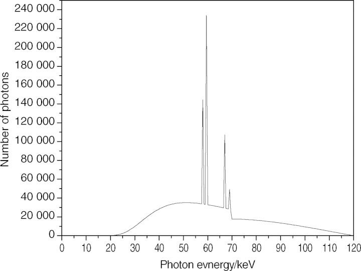
Figure 1 shows a 120-keV X-ray spectrum analysed using the SRS-78 program (Birch and Marshall, Institute of Physics and Engineering in Medicine, 1997) to simulate the beam quality of the CT system. A bow-tie filter was estimated from the calculation based on the dose difference per unit distance from the centre of the CT system. As shown in Eq. 1, the normalisation factor (NF), which was used to convert simulation results into experimental data, was defined by the ratio of the dose (Ksim) evaluated by simulation to the measured dose (Kmea) under the same conditions. In both the simulation and the experiment used to obtain the NF, an ionisation chamber was positioned in the centre of the CT system without any phantom or shielding. Since the conditions of simulation and measurement were identical to each other, the NF value was independent of positions in the field of view.
Figure 1.
X-ray spectrum from tungsten target and aluminium filter at 120 kVp.
The absorbed dose in the phantom was calculated by the NF (mGy/Photon) and other factors as shown in Eq. 2:
| 1 |
| 2 |
where Dsim is the dose evaluated by the simulation and N is the number of rotations.
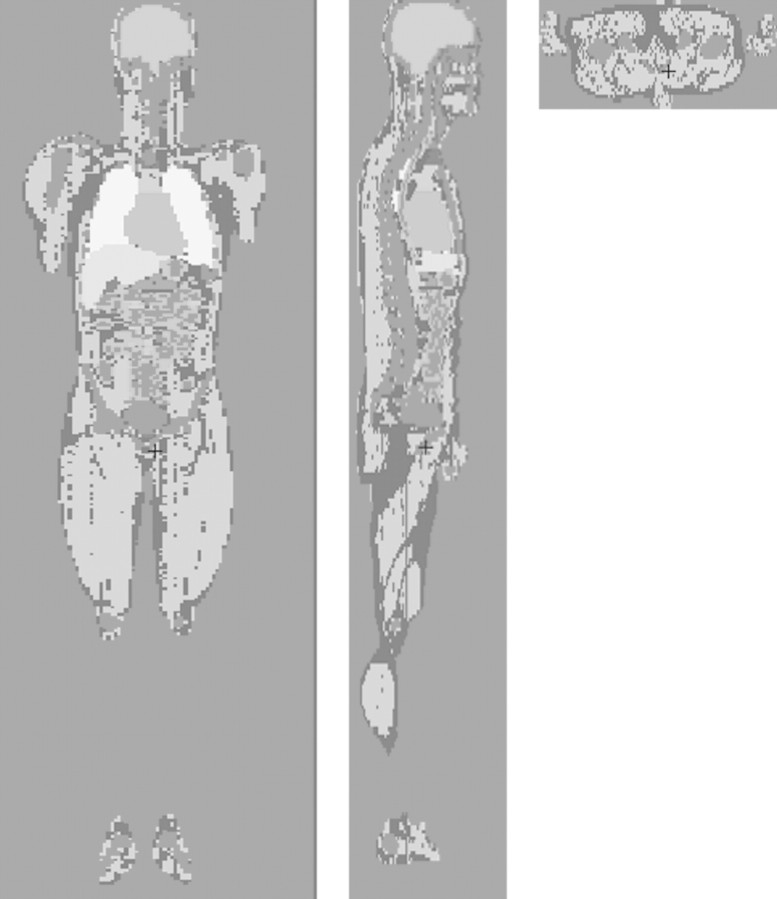
Figure 2 shows the simulations of the phantom, ionisation chamber and bismuth shielding used to calculate the absorbed dose in the phantom. Figure 2a is an axial view showing the ionisation chamber, exterior cap and PMMA phantom without bismuth shielding. Figures 2b and c are the frontal views of the phantom with bismuth shielding and its magnified picture, respectively. Using the MCNPX code, the simulation result with the PMMA phantoms was compared with that with a realistically voxelised phantom, KTMAN-2 (cf. Figure 3), made by Lee(15).
Figure 2.

Phantom, bismuth shielding and ionisation chamber simulated by MCNPX code. (a) Axial view, (b) frontal view and (c) magnified picture of bismuth shielding on the phantom.
Figure 3.
Korean typical MAN-2 (KTMAN-2) phantom simulated by MCNPX code. (a) Coronal view, (b) sagittal view and (c) axial view.
The effect of the dose reduction achieved by lead and bismuth was also compared. The MCNPX simulation with the lead shielding was carried out under the same experimental conditions as with bismuth.
Experimental conditions
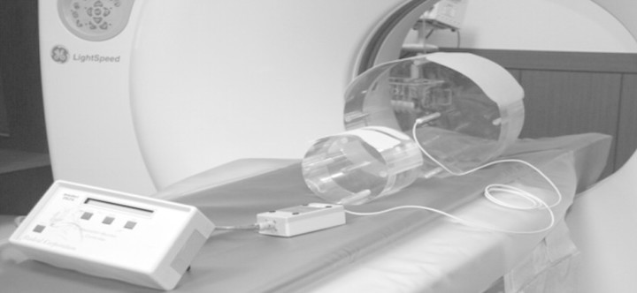
The CT dose was measured by a CT ionisation chamber (Model 20 × 5-3 CT, S/N 21560; Radcal corporation, Monrovia, USA) in a PMMA phantom (head and body phantom, 76-419-4150, Fluke Biomedical) that had five measurement points at the centre and periphery. The chamber consists of C552, electrode and polyacetal exterior cap. C552 was an air-equivalent wall composed of hydrogen, carbon, oxygen, fluorine and silicon. The length and active volume of the chamber were 10 cm and 3 cm3, respectively. The density of the exterior cap and C552 were 1.41 and 1.76 g cm−3, respectively. The PMMA head and body phantoms are made of solid acrylic and have five cylindrical holes located at the centre and at directions of 12, 3, 6 and 9 o'clock from the centre. The diameters of the head and body phantoms were 16 and 32 cm, respectively. The diameter of the holes was 1.31 cm, and each hole was 1 cm from the edge of the phantom. This locations were close to the eyes, the thyroid and inside of the breast. Bismuth shielding for eyes, thyroid and breast was made by F and L Medical Products (Vandergrift, PA, USA). The sizes of the eye, thyroid and breast shielding were 14 × 3.5 × 0.32 cm, 15 × 8.5 × 0.48 cm and 53 × 20.5 × 0.43 cm, respectively. The density of the bismuth shielding was approximately 0.7 g cm−3 (Figure 4). Each shielding was attached around the phantoms as shown in Figure 5.
Figure 4.
Ionisation chamber, PMMA phantom and bismuth shielding for CT dose measurement.
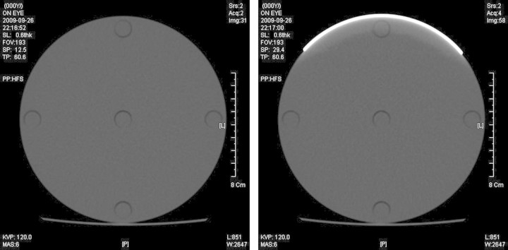
Figure 5.
CT scan images of the PMMA head phantom for 120 kVp and 6 mAs. (a) without shielding and (b) with eye shielding.
The sensitive volume of the ionisation chamber was aligned with the centre of the CT system. The dose was measured five times at each hole to calculate an average value. The doses with and without bismuth shielding around the PMMA phantom were compared to calculate the dose reduction. For the dose measurements of the head, CT scanning was performed with eye and thyroid shielding on the PMMA head phantom. For the dose measurements of the body, the PMMA body phantom was used with breast shielding. The X-ray high voltages were 120 and 80 kVp, which are standard values in X-ray diagnosis. The current and exposure time were 100 mA and 0.1 s, respectively, which are common conditions in CT examination.
RESULTS
As shown the Tables 1–3, for both bare and shielded PMMA phantoms, the differences in dose between the experiment and simulation were 9 % or less. For the eye dose, the averaged doses measured and simulated without the shielding were 3.26 and 3.43 mGy, and those with the shielding were 2.87 and 3.02 mGy, respectively, at 120 kVp. At 80 kVp, the averaged dose measured and simulated without the shielding were 1.15 and 1.21 mGy, and those with shielding were 0.98 and 1.02 mGy, respectively. For the thyroid dose, the values of the averaged dose measured and simulated without the shielding were 3.26 and 3.43 mGy, and those with shielding were 2.82 and 3.00 mGy, respectively, at 120 kVp. The measured and simulated doses were reduced from 1.15 and 1.21 mGy to 0.95 and 1.01 mGy, respectively, at 80 kVp. For the breast study, the averaged doses measured and simulated with shielding were 1.55 and 1.53 mGy and those without shielding were 1.34 and 1.34 mGy, respectively, at 120 kVp. The averaged doses measured and simulated at 80 kVp were reduced from 0.53 and 0.50 mGy to 0.44 and 0.43 mGy, respectively.
Table 1.
The differences in dose values between experiment and simulation with and without bismuth shielding of eye on the head phantom (mGy).
| Position | kVp | Head phantom without bismuth |
Head phantom with bismuth |
||||
|---|---|---|---|---|---|---|---|
| Mea | Sim | Differ (%) | Mea | Sim | Differ (%) | ||
| Centre | 120 | 3.24 | 3.41 | −5.52 | 2.88 | 3.03 | −4.90 |
| 80 | 1.08 | 1.13 | −5.01 | 0.93 | 0.97 | −4.47 | |
| 12 h | 120 | 3.45 | 3.59 | −4.06 | 2.27 | 2.29 | −0.92 |
| 80 | 1.26 | 1.29 | −2.43 | 0.68 | 0.65 | 3.85 | |
| 3 h | 120 | 3.24 | 3.43 | −5.83 | 3.10 | 3.29 | −6.23 |
| 80 | 1.14 | 1.24 | −8.79 | 1.11 | 1.18 | −6.41 | |
| 6 h | 120 | 3.04 | 3.27 | −7.56 | 2.97 | 3.20 | −7.91 |
| 80 | 1.07 | 1.14 | −6.05 | 1.04 | 1.12 | −8.09 | |
| 9 h | 120 | 3.30 | 3.44 | −4.09 | 3.12 | 3.30 | −5.77 |
| 80 | 1.17 | 1.24 | −5.52 | 1.13 | 1.18 | −4.81 | |
Mea, measurement, Sim, Monte Carlo simulation; Differ, difference between measurement and simulation.
Table 2.
The differences in dose values between experiment and simulation with and without bismuth shielding of thyroid on the head phantom (mGy).
| Position | kVp | Head phantom without bismuth |
Head phantom with bismuth |
||||
|---|---|---|---|---|---|---|---|
| Mea | Sim | Differ (%) | Mea | Sim | Differ (%) | ||
| Centre | 120 | 3.24 | 3.41 | −5.52 | 2.82 | 3.00 | −6.44 |
| 80 | 1.08 | 1.13 | −5.01 | 0.90 | 0.96 | −6.40 | |
| 12 h | 120 | 3.45 | 3.59 | −4.06 | 2.15 | 2.27 | −5.64 |
| 80 | 1.26 | 1.29 | −2.43 | 0.63 | 0.64 | −2.57 | |
| 3 h | 120 | 3.24 | 3.43 | −5.83 | 3.07 | 3.27 | −6.45 |
| 80 | 1.14 | 1.24 | −8.79 | 1.09 | 1.17 | −7.95 | |
| 6 h | 120 | 3.04 | 3.27 | −7.56 | 2.95 | 3.20 | −8.62 |
| 80 | 1.07 | 1.14 | −6.05 | 1.05 | 1.12 | −7.01 | |
| 9 h | 120 | 3.30 | 3.44 | −4.09 | 3.10 | 3.28 | −5.75 |
| 80 | 1.17 | 1.24 | −5.52 | 1.10 | 1.18 | −6.93 | |
Mea, measurement, Sim, Monte Carlo simulation; Differ, difference between measurement and simulation.
Table 3.
The differences in dose values between experiment and simulation with and without bismuth shielding of breast on the body phantom (mGy).
| Position | kVp | Body phantom without bismuth |
Body phantom with bismuth |
||||
|---|---|---|---|---|---|---|---|
| Mea | Sim | Differ (%) | Mea | Sim | Differ (%) | ||
| Centre | 120 | 0.95 | 0.97 | −2.28 | 0.81 | 0.83 | −2.75 |
| 80 | 0.27 | 0.26 | 5.14 | 0.22 | 0.21 | 4.22 | |
| 12 h | 120 | 1.75 | 1.70 | 2.68 | 1.03 | 1.01 | 1.81 |
| 80 | 0.62 | 0.58 | 6.45 | 0.28 | 0.27 | 3.74 | |
| 3 h | 120 | 1.75 | 1.71 | 2.67 | 1.66 | 1.64 | 1.33 |
| 80 | 0.62 | 0.58 | 6.12 | 0.58 | 0.56 | 2.99 | |
| 6 h | 120 | 1.51 | 1.54 | −1.95 | 1.50 | 1.53 | −2.14 |
| 80 | 0.51 | 0.52 | −0.16 | 0.50 | 0.51 | −3.40 | |
| 9 h | 120 | 1.77 | 1.73 | 2.39 | 1.68 | 1.68 | 0.36 |
| 80 | 0.63 | 0.59 | 7.52 | 0.62 | 0.57 | 8.94 | |
Mea, measurement, Sim, Monte Carlo simulation; Differ, difference between measurement and simulation.
For the bare phantom, the dose was highest at the 12 o'clock and lowest at the 6 o'clock position in all cases. This positional dependency of dose was due to the radiation attenuation in the couch. The dose deposited in the body phantom was much lower than that deposited in the head phantom since the dose attenuation in the phantom was proportional to the size of the phantom. Figure 6 shows that the bismuth shielding reduced the dose by 1.2 to 55 % depending on the measurement position, X-ray tube voltage and type of shielding.
Figure 6.
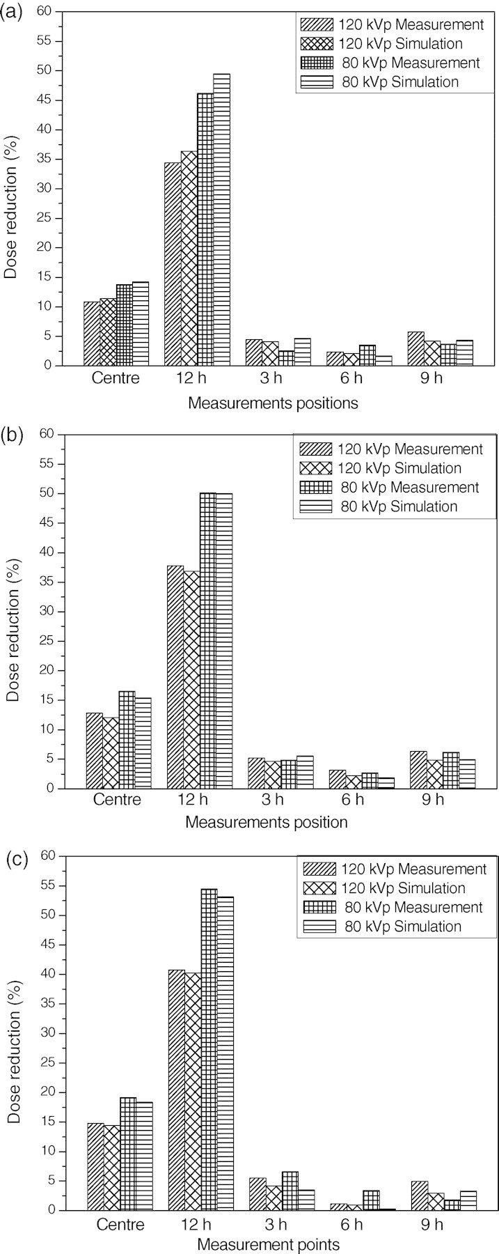
Dose reductions achieved using bismuth shielding for (a) eyes, (b) thyroid and (c) breast.
The dose reductions were highest for the 12 o'clock position since it was closest to the bismuth shielding. The average dose reduction value was at about 34 − 46 % and 41 − 55 % at the 12 o'clock positions of the head and body phantom depending on the tube voltages and types of shielding, respectively.
The dose reductions at the centre were approximately one-third of those at 12 o'clock, and there were only slight reductions at the other peripheral positions. It was concluded that the differences between dose reductions at each evaluation point were related to the distance from the area covered by bismuth shielding. At 12 o'clock and the centre position, the dose reduction was inversely proportional to the X-ray high voltage since the stopping power of the bismuth shielding decreases with X-ray energy.
Due to the radiation attenuation in the bismuth shielding, the reconstructed CT image can become distorted. As shown in the Figure 5, the image distortion due to the bismuth shielding was limited in the range of 1 cm from the shielding, and hence it is encouraged to have a distance of >1 cm between the shielding and the critical organs to be diagnosed.
The amounts of doses for PMMA and KTMAN-2 have been compared in Table 4. The doses for the PMMA phantom measured by the ionisation chamber and those for the breast of the KTMAN-2 phantom were multiplied by the ratio of the total cross-sectional area to the X-ray exposed area of the ionisation chamber or the breast because all the area of eyes and thyroid were exposed to X rays while only partial area of the ionisation chamber and breast was in the angular range of incident X rays. The difference of doses for PMMA and KTMAN-2 was approximately 1 % for eye, 38 % for thyroid and 9 % for breast. For the eye, the location of the organ was close to that of the hole located in the 12 o'clock position of the PMMA head phantom and the whole size of the head in KTMAN-2 was also close to that in the PMMA phantom. In the result, the difference of doses between the 12 o'clock position of the PMMA head phantom and the eye of KTMAN-2 was negligible. However, the thyroid of KTMAN-2 was located near the centre and the size of the neck in KTMAN-2 was much smaller than that of the PMMA head phantom, and hence the difference of thyroid doses between the two phantoms was not small. In the case of breast, the thicknesses of the body in KTMAN-2 and that in the PMMA phantom were close to each other, but the location of the breast in KTMAN-2 and that of the hole in the PMMA phantom was not exactly same resulting in a difference in the estimated doses.
Table 4.
The differences in dose using PMMA and realistic voxel phantom (mGy).
| PMMA (12 h) | KTMAN-2 | Difference (%) | |
|---|---|---|---|
| 120 kVp | |||
| Head | 5.99 | 6.03 | 0.67 |
| Thyroid | 5.99 | 9.62 | −37.73 |
| Breast | 3.15 | 3.49 | −8.31 |
| 80 kVp | |||
| Head | 2.15 | 2.12 | 1.42 |
| Thyroid | 2.15 | 3.44 | −37.50 |
| Breast | 0.48 | 0.44 | 9.09 |
As shown in Table 5, the dose reduction by bismuth shielding was compared with that by lead shielding with same size, density and thickness. The reduced doses were calculated by the MCNPX code at five points of the PMMA phantom and averaged. The simulation results showed that the difference in the dose reductions by the two materials was less than less than 2–3 %.
Table 5.
The differences in dose reductions using bismuth and lead for head and body phantoms.
| 120 kVp | Shielding material | Averaged dose with shielding | Dose reduction (%) |
|---|---|---|---|
| Head | Bismuth | 3.02 | 11.95 |
| Lead | 2.95 | 13.99 | |
| Thyroid | Bismuth | 3.00 | 12.54 |
| Lead | 2.94 | 14.29 | |
| Breast | Bismuth | 1.34 | 12.42 |
| Lead | 1.31 | 14.38 |
DISCUSSION
Since the introduction of CT in the 1970s, the use of CT has significantly increased. With the development of MDCT, the importance of patient protection has been raised. Thus, in this paper, the effects of bismuth shielding for various specific points in the head and body phantoms during CT examination were evaluated and verified. The amount of dose reduction was strongly dependent on the positions. In particular, the dose reduction was highest at the 12 o'clock position, while there were almost no dose reductions at the 3, 6 and 9 o'clock positions. Therefore, it is important to apply bismuth shielding for most CT examinations to selectively protect critical organs such as eyes, thyroid and breast located near the surface, which decreases the probability of side effects such as cataracts and thyroid and breast cancer after multiple CT exams. Bismuth shielding should be selectively located to avoid significant degradation of image quality. If the shielding is >1 cm away from the organ to be diagnosed, the artefact caused by the shielding is minimised. In addition, before applying the shielding to patients, it is necessary to consult with radiologists in order to guarantee that the artefacts caused by the shielding are acceptable in the medical diagnosis.
Both exposure dose and dose reduction were dependent on the X-ray tube voltage because the X-ray energy was inversely proportional to the attenuation in phantom and bismuth shielding. However, there was no perfect recommendation for the proper voltage for optimising image quality and dose reduction because each clinic has its own protocols, scan controlling techniques and equipment for each patient.
The simulation result was well matched with experimental data, and hence it was concluded that it was reasonable to use simulation for the dose estimation of complex designs that were difficult to be tested by experiments. The simulation results of the PMMA and KTMAN-2 phantoms were almost the same for eye and breast, but different for thyroid due to the discrepancy of the locations of the organs and the sizes of the phantoms. Therefore, the simulation result using the PMMA phantom was applicable to an actual patient for eye and breast, but not for thyroid. In general, the doses of some organs near surface such as eye and breast could be calculated using the PMMA phantom and other organs whose location and size were different from those of the PMMA phantom could be estimated using a realistically voxelised phantom such as KTMAN-2.
The dose reductions achieved by bismuth and lead, which were well-known materials for radiation protection, were compared. The difference of the dose reduction was about 2 ∼ 3 % in all cases. This difference is very much like that of the results of other investigators(3).
There were limitations in this research. First, the effect of the bismuth shielding could be further studied from the viewpoint of image quality. The dose reduction using the bismuth shielding was proved to be significant and the image distortion due to the shielding was minimal if the distance between phantom and shielding was >1 cm, but the result may be changed depending on the experimental conditions, such as space-modulated X-ray exposure in an automated CT system to improve the reconstructed image quality with shielding. A detailed study of the relationship between the image quality and the thickness of the bismuth shielding with an automated exposure system is planned.
Second, the adult model was focused upon during this study. However, since the radiosensitivity of paediatric patients is higher than that of adults, the effect of dose reduction with bismuth is also important for children. In the future, therefore, the effect of dose reduction with bismuth shielding for paediatric patients will be studied.
CONCLUSION
In this paper, the effective performance of shielding used to reduce the unnecessary radiation dose of CT examinations has been reported. (1) With proper distance between critical organs and the shielding, the dose of the critical organs could be significantly reduced without degrading the image quality; (2) Bismuth and lead showed similar performance as shielding materials; and (3) For eye and breast, the simulation results using the PMMA phantom were similar with those using a realistically voxelised phantom, but this was not applicable for thyroid whose location and the amount of surrounding material were different for each phantom.
FUNDING
This work was supported by a 3N Researcher Program through the National Research Foundation of Korea (NRF) funded by the Ministry of Education, Science and Technology.
ACKNOWEDGEMENTS
The authors would like to thank the head and members of the radiology department, Kyung Hee Medical Center, for providing its MDCT facility.
REFERENCES
- 1.International Commission on Radiological Protection. Managing patient dose in multi-detector computed tomography (MDCT) 2007 ICRP Publication 102. Ann. ICRP. [Google Scholar]
- 2.Perisinakis K., Raissaki M., Tzedakis A., Theocharopoulos N., Damilakis J., Gourtsoyiannis N. Reduction of eye lens radiation dose by orbital bismuth shielding in pediatric patients undergoing CT of the head:a Monte Carlo study. Med. Phys. 2007;32:1024–1030. doi: 10.1118/1.1881852. [DOI] [PubMed] [Google Scholar]
- 3.Hopper K. D., Neuman J. D., King S. H., Kunselman A. R. Radioprotection to the eye during CT scanning. AJNR Am. J. Neuroradial. 2001;22:1194–1198. [PMC free article] [PubMed] [Google Scholar]
- 4.McLaughlin D. J., Mooney R. B. Dose reduction to radiosensitive tissues in CT. Do commercially available shields meet the user's needs? Clin. Radiol. 2003;59:446–450. doi: 10.1016/j.crad.2003.10.016. [DOI] [PubMed] [Google Scholar]
- 5.McCollough C. H., Bruesewitz M. R., Kofler J. M. CT dose reduction and dose management tools: overview of available options. Radiographics. 2006;26:503–512. doi: 10.1148/rg.262055138. [DOI] [PubMed] [Google Scholar]
- 6.Fricke B. L., Donnelly L. F., Frush D. P., Yoshizumi T., Varchena V., Poe S. A., Lucaya J. In-plane bismuth breast shields for pediatric CT: effects on radiation dose and image quality using experimental and clinical data. AJR Am J Roentgenol. 2003;180:407–411. doi: 10.2214/ajr.180.2.1800407. [DOI] [PubMed] [Google Scholar]
- 7.Coursey C., Frush D. P., Yoshizumi T., Toncheva G., Nguyen G., Greenberg S. B. Pediatric chest MDCT using tube current modulation: effect on radiation dose with breast shielding. AJR Am J Roentgenol. 2008;190:W54–W61. doi: 10.2214/AJR.07.2017. [DOI] [PubMed] [Google Scholar]
- 8.Kalra M. K., Dang P., Singh S., Shepard J. O. In-plane shielding for CT: effect of off-centering, automatic exposure control and shield-to-surface distance. Korean J. Radiol. 2009;10:156–163. doi: 10.3348/kjr.2009.10.2.156. [DOI] [PMC free article] [PubMed] [Google Scholar]
- 9.Hohl C., Wildberger J. E., Sub C., Thomas C., Muhlenbruch G., Schmidt T., Honnef D., Gunther R. W., Mahnken A. H. Radiation dose reduction to breast and thyroid during MDCT: effectiveness of an in-plane bismuth shield. Acta Radiol. 2006;47(6):562–567. doi: 10.1080/02841850600702150. [DOI] [PubMed] [Google Scholar]
- 10.Geleijns J., Artells M. S., Veldkamp W. J. H., Tortosa M. L., Cantera A. C. Quantitative assessment of selective in-plane shielding of tissues in computed tomography through evaluation of absorbed dose and image quality. Eur. Radiol. 2006;16:2334–2340. doi: 10.1007/s00330-006-0217-2. [DOI] [PubMed] [Google Scholar]
- 11.Ngaile J. E., Uiso C. B. S., Msaki P., Kazema R. Use of lead shields for radiation protection of superficial organs in patients undergoing head CT examinations. Radiat. Prot. Dosimetry. 2008;130(4):490–498. doi: 10.1093/rpd/ncn095. [DOI] [PubMed] [Google Scholar]
- 12.Yilmaz M. H., Albayram S., Yasar D., Ozer H., Adaletli I., Selcuk D., Akman C. Female breast radiation exposure during thorax multidetctor computed tomography and the effectiveness of bismuth breast shield to reduce breast radiation dose. J. Comput. Assist. Tomogr. 2007;31:138–142. doi: 10.1097/01.rct.0000235070.50055.e6. [DOI] [PubMed] [Google Scholar]
- 13.Honnef D., Mahnken A. H., Haras G., Wildberger J. E., Staatz G., Das M., Barker M., Stanzel S., Gunther R. W., Hohl C. Pediatric multidetector computed tomography using tube current modulation and a patient image gallery. Acta. Radiol. 2008;49(4):475–483. doi: 10.1080/02841850801950095. [DOI] [PubMed] [Google Scholar]
- 14.Lechel U., Becker C., Langenfeld-Jager G., Brix G. Dose reduction by automatic exposure control in multidetector computed tomography: comparison between measurement and calculation. Eur. Radiol. 2008;19:1027–1034. doi: 10.1007/s00330-008-1204-6. [DOI] [PubMed] [Google Scholar]
- 15.Lee C. KTMAN-2 (Korean Typical MAN-2), Korean Voxel Phantom. Available on http://mcnp-green.lanl.gov/publication/mcnp_publications.html#medicalphysics . [Google Scholar]


