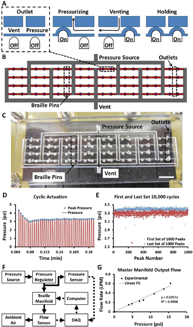
Figure 2. Micropneumatic Device.
A) The circuit comprises 32 subunits consisting of two braille pins and one outlet. Four different states are possible depending on the combination of braille pins actuated. B) Schematic of the PDMS device with 32 independently addressable outputs (yellow circles) fed from a single pressure source via small rounded microchannels (red) and large square channels (white). C) Actual image of the PDMS device interfaced with the braille display. Scale Bar: 5 mm. D) Pressure profile (red line) of a single output actuated at 5 Hz (peaks are marked with blue crosses). E) Comparison of first and last set of 1,000 peaks of a test of 10,000 cycles. F) Schematic of experimental setup for determining fluidic resistance of a single flow path through the pneumatic manifold. G) Flow rates of pressurized air for a range of pressures for a master manifold with 32 outputs. The slope of the linear fit provides the inverse of the fluidic resistance.

