

Abstract
Intracochlear electric fields arising out of sound-induced receptor currents, silent currents, or electrical current injected into the cochlea induce transmembrane potential along the outer hair cell (OHC) but its distribution along the cells is unknown. In this study, we investigated the distribution of OHC transmembrane potential induced along the cell perimeter and its sensitivity to the direction of the extracellular electric field (EEF) on isolated OHCs at a low frequency using the fast voltage-sensitive dye ANNINE-6plus. We calibrated the potentiometric sensitivity of the dye by applying known voltage steps to cells by simultaneous whole-cell voltage clamp. The OHC transmembrane potential induced by the EEF is shown to be highly nonuniform along the cell perimeter and strongly dependent on the direction of the electrical field. Unlike in many other cells, the EEF induces a field-direction-dependent intracellular potential in the cylindrical OHC. We predict that without this induced intracellular potential, EEF would not generate somatic electromotility in OHCs. In conjunction with the known heterogeneity of OHC membrane microdomains, voltage-gated ion channels, charge, and capacitance, the EEF-induced nonuniform transmembrane potential measured in this study suggests that the EEF would impact the cochlear amplification and electropermeability of molecules across the cell.
Introduction
Intracochlear electric fields are introduced within the organ of Corti by sound-induced receptor currents, silent currents (1,2), or electrical current injected into the cochlea via, e.g., cochlear implant electrodes (3) or electrodes in animal experiments (4,5). This extracellular electric field (EEF) induces transmembrane potential along the outer hair cells (OHCs), whose distribution along the cell is unknown. The OHCs constitute one of two kinds of mechanosensitive hair cells in the mammalian cochlea. They play an important role in enhancing sound-induced vibrations inside the hearing organ by means of somatic electromotility (6). OHC somatic electromotility is an electromechanical transduction phenomenon whereby cellular length changes are produced at audio frequencies in response to changes in their transmembrane potential and charge displacement. This process is reciprocal, i.e., charge displacement is induced by stretching of the basolateral membrane (7). It is thought to arise through voltage-gated conformational changes in a membrane protein that has been identified as prestin (8). Although it is known that OHC somatic electromotility is largest for EEF applied along the OHC axis, and smallest for EEF perpendicular to the OHC axis (9), the quantitative dependence of the EEF-induced OHC transmembrane potential on the EEF direction is not known.
The OHC plasma membrane is functionally partitioned. The apical part performs the task of mechanoelectrical transduction, converting the deflection of its stereocilia into ionic current; the lateral membrane performs electromechanical transduction in the form of somatic electromotility (8,9); and the basal part performs neurotransmission (10). Whereas the lateral membrane of the OHC contains nearly all of the prestin molecules that are responsible for somatic electromotility, the basal membrane houses most of the voltage-gated ion channels. The lateral membrane is also composed of structural microdomains. This heterogeneity may underlie similar variability in the mechanical activity of the lateral membrane. Kachar et al. (11) observed local variation in the direction that microbeads moved along the surface of the electrically excited OHC. Santos-Sacchi (12) showed that the microdomains are functionally independent and the voltage characteristics of the elementary motors differ from those obtained through whole-cell measures. Furthermore, the OHC charge and capacitance vary along the cell membrane (13). Additionally, the membrane cholesterol composition of OHC plasma membrane is nonuniform, which could affect the conductivity of the ion channels along the OHC perimeter (14). Thus, the distribution of transmembrane potential along the OHCs has the potential to influence several aspects of hearing, including cochlear amplification and the electropermeability of molecules into the cell.
In this study, we measured the OHC transmembrane potential induced by EEF at a low frequency of 3 Hz using a nanosecond-response fast voltage-sensitive dye (nsFVSD), ANNINE-6plus (15). Voltage-sensitive dyes act as cellular voltmeters, allowing direct measurement of changes in the transmembrane potential (16). One of the desirable features of the optical approach is that it allows one to record spatiotemporal signals from multiple sites simultaneously. Although voltage-sensitive dyes have been routinely used to study neuronal activity (17) and to determine the distribution of electrically induced transmembrane potential in other cells (18), they have rarely been used to visualize transmembrane-potential changes in cochlear cells or tissues. Nakagawa et al. (19) used voltage-sensitive dyes to measure the phase delay in propagation of a voltage signal applied to the base of an isolated OHC. Their work involved the application of whole-cell voltage or current clamp and measurement of the resulting transmembrane potentials along the OHC. In this study, we measured the transmembrane potentials along the OHC perimeter induced by EEF, and its quantitative dependence on the direction of the electric field. We show that the EEF induces a highly nonuniform distribution of OHC transmembrane potential along the cell perimeter. Unlike the case with many other cells, the EEF also induces a field-direction-dependent intracellular potential in the cylindrical OHC, perhaps owing to the heterogeneous distribution of OHC membrane resistance. We also predict that without this induced intracellular potential, there would be negligible somatic electromotility resulting from the EEF.
Materials and Methods
Ethical approval
All procedures in this study were approved by the Institutional Animal Care and Use Committee of Oregon Health and Science University.
Tissue-cultured HEI-OC1 cells
The auditory cell line HEI-OC1 was kindly provided by Dr. Federico Kalinec (House Research Institute (formerly known as House Ear Institute), Los Angeles, CA). The cells were cultured in high-glucose Dulbecco’s modified Eagle’s medium (Invitrogen, Carlsbad, CA) supplemented with 10% fetal bovine serum (FBS) and 10 μg/L γ-interferon (Invitrogen), and maintained at 33°C in a humidified 10% CO2 incubator. Twenty-four hours before analysis, 2 × 10⁴ cells were plated per well in four-well microscope slides.
OHC isolation
Adult guinea pigs (250–300 g) with positive Preyer’s reflex were anesthetized by intramuscular injection of an anesthetic mixture (60 mg/ml ketamine, 2.4 mg/ml xylazine, and 1.2 mg/ml acepromazine in saline) at a dose of 1 ml/kg and killed by decapitation. The cochleae were rapidly removed from the bulla and dissected in a petri dish filled with a standard artificial perilymph composed of (mM) 144 NaCl, 4 KCl, 1.3 CaCl2, 0.9 MgCl2, 0.7 Na2HPO4, 10 HEPES, and 5.6 glucose. The osmolarity of the solution was adjusted to 304 mOsmol/l with glucose and the pH was adjusted to 7.4 with NaOH. All procedures were performed at room temperature. The organ of Corti was dissected and digested with dispase I (1.0 mg/ml) for 12 min. A few drops of the solution containing the dissociated OHCs were placed on a microscope slide coated with poly-L-lysine. The cells were allowed to settle and attach to the bottom of the chamber.
Dye loading
The cell preparation was bathed in an artificial perilymph solution (20). The nsFVSD ANNINE-6plus (Dr. Hinner & Dr. Hübener Sensitive Dyes, Farbstoffe) was added to the bath solution at a concentration of 5 μg/ml (21). The cells were incubated for 5 min with this dye solution, washed twice with the bath solution, and transferred to the microscope.
Solutions
Bath solutions containing (mM) 142 NaCl, 5 KCl, 1.5 CaCl2, 2 MgCl2, 10 HEPES, and 5.6 D-glucose were adjusted to a pH of 7.4 with NaOH and osmolarity to 304 mOsmol/l with D-glucose. Pipette solutions containing(mM) 148 KCl, 0.5 CaCl2, 2 MgCl2, 10 HEPES, and 1 EGTA (final Ca2+ concentration of 50 nM) were adjusted to pH 7.4 with KOH, and osmolarity was adjusted to 298 mOsmol/l with D-glucose.
Electrical excitation using an electrode pair
An AgCl cylindrical wire electrode pair (each 125 μm in diameter; use of these thick wires eliminated charge-density-dependent bubbles at their surface) separated by ∼1 mm was used to provide the electrical excitation. The electric field applied was ∼1–2 mV/μm. (This is proportional to V/d, where V is the amplitude of the voltage applied to the electrodes and d is the interelectrode spacing). The electrodes can be approximated as parallel wires, and thus the electrical field is oriented in the direction perpendicular to those wires. The wire electrode pair, and hence the resulting electric field, was positioned in the plane of the chamber (parallel to the microscope slide) containing the isolated cells. The pCLAMP-10 data acquisition system was used to apply square or sine wave voltage input to the wires at ∼10 V and 3 Hz frequency. The low alternating current (AC) frequency used here is not due to a limitation of nsFVSD speed. We chose the low frequency because we used a CCD camera for the recording to allow for simultaneous capture of the entire cell in each frame. The 3 Hz frequency used here was sufficient for the scope of this work, in which we ignored the dynamics due to cell capacitance.
Patch clamping
Patch-clamp measurements were done on cultured HEI-OC1 cells to apply a known transmembrane potential for calibrating the voltage-sensitive dye ANNINE-6plus used in this study. The patch pipettes were pulled with a puller (P80/PC; Sutter Instrument) in four steps from borosilicate capillaries (WPI, 1B150F-4) with initial resistance of 4–5 mohm in our regular Na+-rich bath and K+-rich pipette solutions. Data acquisition for electrophysiology was done using Axon Instruments controlled by pCLAMP 10.2 and Clampex software. The MultiClamp 700B amplifier was used with the patch-clamp head stages. Two Sutter Instrument micromanipulators were integrated with this system and remotely controlled.
Fluorescent imaging
The fluorescence excitation light was provided by the X-Cite 120Q microscope light source system. We used the nsFVSD ANNINE-6plus and the Semrock Di-A-A-ZHE filter set with excitation spectrum 430–480 nm and emission spectrum 565–645 nm. Calculations similar to those described by Kuhn and Fromherz (22) for the dye showed that this filter set is nearly optimized for the use of ANNINE-6plus dye. The fluorescence intensity decreases for cell depolarization and increases for cell hyperpolarization for this dye and filter set. The strategy used here for filter selection was to maximize the response of the dye. An alternative filter-selection strategy would be to maximize the sensitivity up to 25% per 100 mV, but at the expense of much reduced intensity (16).
Image recording and postprocessing
A Hamamatsu ORCA CCD camera connected to one port of an AxioExaminer Zeiss upright microscope was used to record images at the rate of 16 frames per second (using 2-pixel binning). The CCD camera recorded fluorescence images of the whole cell as a function of time. These images, which were sequential camera frames, were imported into MATLAB (The MathWorks, Natick, MA) as a video file. The whole-cell membrane region was divided into ∼25–50 regions of interest (ROIs). The raw intensity over the ROIs partitioning the cell membrane (IROIraw) was obtained by averaging over each ROI. The background intensity (IBG) in any time frame was determined by selecting a region exclusive of any cell membrane. The intensity over the ROI (IROI) was determined by subtracting the background intensity (IBG) from the raw intensity (IROIraw). The intensity IROI has information about the cell transmembrane potential, which is an alternating component at the frequency of the stimulus, but it is accompanied by a slow change due to photobleaching of the dye over the exposed time period. The intensity change with time due to photobleaching was determined by fitting IROI by a simple polynomial function IROIFIT (see Fig. 1). The fractional change in the intensity over a portion of the cell membrane is thus given by (IROI − IROIFIT) / IROIFIT.
Figure 1.

Data sample showing the intensity over one ROI with background subtracted (IROI) and a polynomial fit for the drop in intensity from photobleaching (IROIFIT). The two arrows point to the start and end of the 3 Hz sinusoidal EEF excitation signal. To see this figure in color, go online.
This fractional change in intensity was converted into the local transmembrane potential (ΔφROI) using the calibration Calib, as determined for the ANNINE-6plus dye for our filter setup using simultaneous whole-cell voltage clamp on HEI-OC1 cells. Calib is the fractional change in the fluorescence intensity of the dye for a 100 mV change in the transmembrane potential. The qualitative results presented in this work do not depend on the calibration, but the quantitative values do. Thus,
| (1) |
The peak transmembrane potential in the ROI was obtained over each cycle of the electric field excitation and then averaged over these cycles to give ΔφROI. The procedure was repeated for all ROIs. The phase of the transmembrane potential was determined from ΔφROI(t) at some fixed time t = t∗ for all ROIs. A plot of ΔφROI along with its phase thus gives a snapshot, or single-time picture, of the transmembrane potential versus perimeter in response to the applied alternating electric field. Note that the induced transmembrane potential is independent of the raw fluorescence intensity and depends only on changes in the intensity. The EEF-induced change in the OHC transmembrane potential leads to a change in the length of the cell by means of its somatic electromotility. This length change is expected to recruit more membrane into the individual ROI, which could potentially affect fluorescence measurements. However, the level of electromotility did not affect the fluorescence measurements presented in this study. For a 0.6 μm electromotility length change (see Supporting Material) of a 70-μm-long OHC, the percentage change in length is 0.85%. The change in the size of the ROI is also 0.85%. For a ∼10 pixel ROI, as used in this study, this change is <0.1 pixel, which is small and did not affect the fluorescence measurements presented here.
Results
Calibrating the dye sensitivity using simultaneous whole-cell voltage clamp and nsFVSD
The sensitivity of a voltage-sensitive dye depends on several factors, such as the setup and filters, staining time, concentration, time between staining and measurement, cell type, and the particular stock of dye used in the experiment. Thus, it is important to calibrate the sensitivity of the dye.
We calibrated the sensitivity of the nsFVSD ANNINE-6plus using simultaneous whole-cell voltage clamp plus fluorescent imaging in cultured HEI-OC1 cells, similar to the technique suggested in Carlson and Coulter (23). This dye has a very fast response time, on the order of less than a few nanoseconds (15). The measured data are shown in Fig. 2 for four HEI-OC1 cells. Fig. 2, A, B, E, and F, show the raw intensity (mean over the cell perimeter) minus the background. A continuous nearly exponential drop in intensity due to photobleaching was removed by function-fit. The red curves in these panels show the exponential fit to the data. The steps in the insets in Fig. 2, A, B, and F, show the time frames in which the whole-cell clamp voltage was changed from −70 mV to +70 mV (first step), +70 mV to −70 mV (second step), and −70 mV to 0 mV (third step). In Fig. 2 E, the whole-cell clamp voltage was changed from −70 mV to +70 mV (one step only). The percentage change in intensity with the applied voltage steps is derived by subtracting the exponential fit from the data in Fig. 2, A, B, E, and F, and dividing by the corresponding exponential fit, as discussed in the Materials and Methods section. These data are shown in Fig. 2, C, D, G, and H. It may be noticed that the curve fit for photobleaching is not perfect and thus the curves shown in Fig. 2, C, D, G, and H are not perfectly flat where no voltage steps are given. The fluorescence intensity decreases upon cell depolarization and increases with cell hyperpolarization for the filter set and dye chosen. The percentage change in intensity of the dye was determined to be Calib ≈ 5–5.7% per 100 mV in the cultured HEI-OC1 cells based on the data shown in Fig. 2, C, D, G, and H. The ANNINE-6plus dye has been reported to be linear versus voltage (24) for the ranges used in this work. In Fig. 2, C and D, the percentage change for 70 mV change in transmembrane potential (third step) is nearly half of that for a 140 mV change in the transmembrane potential (second step).
Figure 2.

Change in fluorescence intensity of ANNINE-6plus in HEI-OC1 cells in response to step changes to the intracellular voltage applied via simultaneous whole-cell voltage clamp. (A–H) Raw (A, B, E, and F) and percentage (C, D, G, and H) changes in dye intensity are shown as a function of time for four representative cells. It can be seen that the portions of the curve with a slight rise or fall without accompanying step changes in (C, D, G, and H) are due to imperfections in the function-fit in these regions.
Transmembrane potential distribution along the cell perimeter induced by EEF
Theoretical model
The local transmembrane potential induced by the EEF along a cell perimeter is given by the difference between the EEF-induced intracellular potential and the EEF-induced local extracellular potential on the cell membrane (25). If a cell membrane is assumed to be nonconducting, owing to the much larger membrane resistance of a cell compared with the bath resistance, no electric current should enter the cell. However, in reality, a cell is not completely insulated and there is a small current flowing into the cell. This intracellular current will generate a net intracellular potential if the membrane resistance distribution is nonuniform, which is the case for OHC. Predicting the EEF-induced OHC intracellular potential would require knowledge of the OHC membrane heterogeneities, which is beyond the scope of this study. (However, see the Supporting Material for a lumped model of the EEF-induced intracellular potential in a simplified heterogeneous cylindrical cell in which the membrane resistance of the top half differs from that of the bottom half.) The EEF-induced intracellular potential (a single value per cell) is derived from measurements as the mean of the transmembrane potential along the cell membrane (26).
The extracellular potential induced along the plasma membranes of cells placed in an electric field depends only on the EEF and the cell’s geometric properties and orientation, and is governed by the Laplace equation (18). Consider an ellipsoidal cell with semi-axes a, b, and c excited by an electric field at azimuth angle δ and elevation angle γ. The induced extracellular potential along the three-dimensional surface of the cell where α and β are the elevation and azimuth angle made by a point on the cell-membrane surface at its center (derived from Eq. 23 and Fig. 5 of Gimsa and Wachner (27)) is given by
| (2) |
Here E is the strength of the EEF. A cylindrical shape is the limiting case of an infinitely long ellipsoid with b = c; a ≫ b, c.
Figure 5.
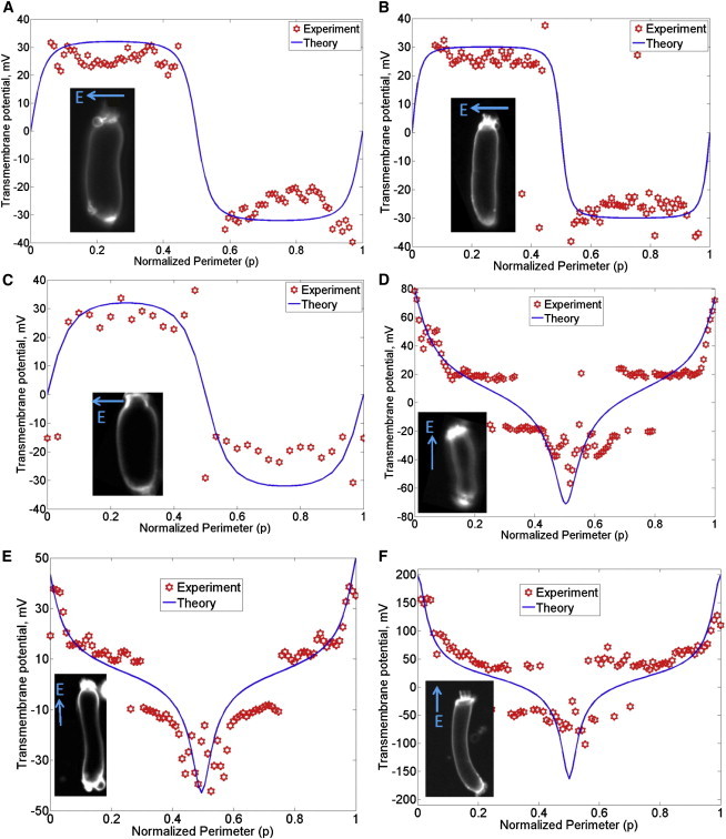
Transmembrane potential along the perimeter of isolated OHCs from guinea pig induced by EEF. Similar results were found in other OHCs (n = 11, including the six shown). Representative plots for six cells are shown here (A-F). The abscissa is the normalized perimeter (p) described in Fig. 3. Images of the OHCs are shown in the insets. The transmembrane potential is proportional to the local percentage change in the fluorescent intensity, and is independent of the raw intensity. The arrow showing the direction of the electric field is perpendicular to the orientation of the two parallel wire electrodes. (D–F) The EEF applied along the axis also induced intracellular potential in OHCs as discussed in the text.
For the purpose of comparison with the experiments reported in this article, the electric field can be assumed to be in the x-y plane, that is, γ = 0 as the wire-electrode pair is positioned in the x-y plane. For γ = 0, the term c cos α also drops out of Eq. 2. This leads to the simplification
| (3) |
The cell geometric parameters and the normalized perimeter p = β/2π are described in the schematic shown in Fig. 3.
Figure 3.

Schematic of a cylindrical cell describing the normalized perimeter (p), the angle of the EEF relative to the axis (δ), the azimuth angle β made by a point on the cell-membrane surface at its center, the half-length a, and the radius b of the cell.
Measured data for HEI-OC1 cells
Among other differences between the HEI-OC1 cultured cells and the OHCs, the HEI-OC1 cells do not have prestin and furthermore they are expected to have uniform membrane resistance along the perimeter. Thus, we first discuss the distribution of transmembrane potential in cultured HEI-OC1 cells in this section.
The normalized perimeter p is the abscissa in Figs. 4–6. The EEF-induced transmembrane potential along the perimeter of HEI-OC1 cells is shown in Fig. 4 for four cells (out of n > 10 cells tested). The measured data are represented by red markers and the model is shown by solid curves. The orientation of the EEF relative to the HEI-OC1 cell is δ = 90° for the data shown in Fig. 4 A, δ = 10° for the data shown in Fig. 4 B, δ = 5° for the data shown in Fig. 4 C, and δ = 40° for the data shown in Fig. 4 D. The length and diameter of the cells shown in Fig. 4 were measured according to their extent on the camera image, as follows: L = 40 μm, D = 16 μm for the HEI-OC1 cell shown in Fig. 4 A; L = 80 μm, D = 14 μm for the cell shown in Fig. 4 B; L = 64 μm, D = 14 μm for the cell shown in Fig. 4 C; and L = 28 μm, D = 13 μm for the cell shown in Fig. 4 D. The respective EEF strengths were estimated to be ∼2 mV/μm, 1 mV/μm, 1 mV/μm, and 2 mV/μm. In all cases, including tested cells not shown, the measurements agree very well with theory. Also, there is negligible induced intracellular potential in these cells. Therefore, the transmembrane potential is equal to the negative of extracellular potential on the cell membrane.
Figure 4.
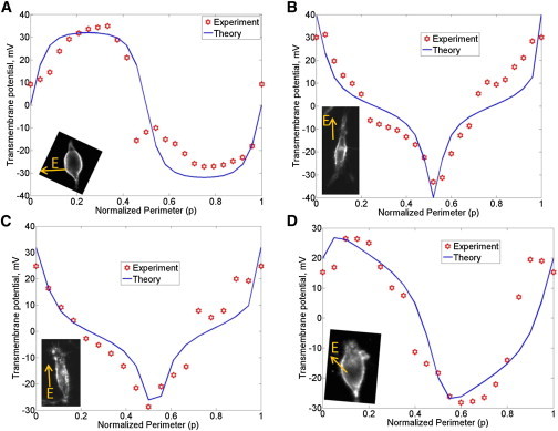
Transmembrane potential along the perimeter of HEI-OC1 cells induced by EEF are shown for four cells (A-D). Similar results were found in many HEI cells (n > 10). The abscissa is the normalized perimeter (p) described in Fig. 3.
Figure 6.

Simulated OHC transmembrane potential along the perimeter assuming the OHC as a cylindrical cell of length 70 μm, diameter 10 μm and for EEF strength E = 5 mV/μm, predicted using Eq. 4 for varying angles (δ) of the electric field relative to the cell axis.
Measured data for OHC
Fig. 5 shows the measured transmembrane potential along OHC perimeter in response to EEF. The measured data are represented by red markers (where each data point is from one ROI; see Materials and Methods) and the model is shown by solid curves. In the cells shown, the orientation of the EEF relative to the OHC is δ = 90° for the data shown in Fig. 5, A–C, and δ = 0° for the data shown in Fig. 5, D–F. In Fig. 5, the apical end of the OHC corresponds to p = 0, 1 (and corresponds to β = 0, 2π) and the basal end corresponds to p = 0.5 (and corresponds to β = π), where p = β/2π is the normalized perimeter along the OHC. The length and diameter of the cells shown in Fig. 5 were measured using their extent on the camera image. These values were determined to be L = 60 μm, D = 16 μm for the OHC shown in Fig. 5 A, L = 70 μm, D = 12 μm for the OHC shown in Fig. 5 B; L = 36 μm, D = 16 μm for the OHC shown in Fig. 5 C; L = 54 μm, D = 12 μm for the OHC shown in Fig. 5 D; L = 64 μm, D = 11 μm for the OHC shown in Fig. 5 E; and L = 70 μm, D = 10 μm for the OHC shown in Fig. 5 F. The applied EEF strength for these cells is estimated to be approximately 2 mV/ μm in Fig. 5 A, 2.5 mV/ μm in Fig. 5 B, 2 mV/ μm in Fig. 5 C, 3 mV/ μm in Fig. 5 D, 1.5 mV/ μm in Fig. 5 E, and 5 mV/ μm in Fig. 5 F.
When the EEF is applied at δ = 90° i.e., perpendicular to the OHC axis (Fig. 5, A–C), the induced transmembrane potential on the left half of the cell is equal in magnitude and opposite in phase with the transmembrane potential on the right half of the cell. On the other hand, when the EEF is applied along the OHC axis (Fig. 5, D–F), the apical transmembrane potential is opposite in phase, but of larger magnitude, than the basolateral transmembrane potential. For EEF applied along the OHC axis, the induced OHC intracellular potential is 10 mV for the OHC shown in Fig. 5 D, 5 mV for the OHC shown in Fig. 5 E, and 35 mV for the OHC shown in Fig. 5 F. The 5 mV shift in Fig. 5 E may be close to the noise floor of the voltage-dye setup used here. The induced intracellular potential appears to be proportional to the strength of the EEF times the length of the cell, as well as dependent on the heterogeneity of the cell-membrane resistance (see Supporting Material for a lumped model of the EEF-induced intracellular potential in a simplified heterogeneous cylindrical cell). The heterogeneous OHC membrane resistance is at least partly due to the different apical versus basolateral resistance (28,29). The induced intracellular potential in the isolated OHCs shown in Fig. 5, D–F, could depend on the state of the mechanoelectrical transduction channels at the apex and the basolateral channels. The process of isolating the OHCs could, in general, affect these channels. Isolation of hair cells generally results in the mechanoelectrical transduction channels having a reduced open probability of ∼10% (30). Strictly speaking, it would therefore be necessary to ascertain the state of these channels in the OHCs. However, that was not done in this study due to technical difficulties in performing such an experiment on the same OHCs as used for voltage-dye imaging.
OHC transmembrane potential versus EEF direction—simulation
The induced OHC transmembrane potential for EEF oriented at angle δ relative to the OHC axis in the x-y plane can be considered to be a linear combination of the OHC response to EEF at 0° (on-axis) and 90° (off-axis):
| (4) |
The OHC transmembrane potential response to on-axis EEF is given by setting δ = 0° in Eq. 3 for the extracellular potential on the cell membrane and adding the intracellular potential for the on-axis case:
| (5) |
The OHC transmembrane potential response to EEF applied perpendicular to the axis is given by setting δ = 90° in Eq. 3 and adding zero intracellular potential after the measured data (Fig. 5):
| (6) |
Fig. 6 shows the EEF-induced OHC transmembrane potential simulated using Eq. 4 versus OHC perimeter for various EEF directions. The parameters used in Fig. 6 are OHC length = 2a = 70 μm, OHC diameter = 2b = 10 μm, = 30 mV, and EEF strength E = 5 mV/μm. The EEF-induced transmembrane potential is nonuniform along the OHC perimeter and is strongly dependent on the EEF direction.
Discussion
It is well known that the EEF induces somatic electromotility in OHCs (9,31). OHC somatic electromotility is an electromechanical transduction phenomenon whereby transmembrane potential drives cellular length changes at audio frequencies. However, the details of OHC electromotility resulting from the EEF are not fully understood. Our study shows that in contrast to the whole-cell patch-clamp condition, where the OHC transmembrane potential is uniform and set by the clamp voltage, the EEF-induced transmembrane potential is highly nonuniform and dependent on the EEF direction. We investigated the EEF-induced OHC transmembrane potential, including its dependence on the dimensions and shape of the cell and EEF direction. The mean lateral transmembrane potential (OHC electromotility is expected to be approximately proportional to this quantity) is derived from the distribution of transmembrane potential along OHC perimeter in the Supporting Material. The mean lateral transmembrane potential induced by EEF is negligible if the EEF-induced intracellular potential is zero.
Even in the absence of sound stimulation, silent currents flow from the stria vascularis into the scala and back to the stria vascularis, thus creating complex electric fields in the vicinity of OHCs as described in Zidanic and Brownell (2). Sound-induced vibration of the OHC stereocilia dynamically modulates the silent current as a result of receptor currents flowing through OHCs and leading to the generation of cochlear microphonics and thus AC EEF. Local cochlear microphonics measured in the extracellular space near OHCs has been shown to follow sound-induced motion (32,33). We modeled the global effect of cochlear microphonics by including longitudinal cables representing the three fluid-scalae coupled with receptor currents generated by sound-induced mechanical vibrations (33). In particular, we showed that the extracellular longitudinal electrical coupling across OHCs produces further amplification of the sound-induced vibrations in the cochlea.
Although the AC EEF is generated by the sound-induced receptor currents, the EEF also contributes to the OHC transmembrane potential. Even if the AC EEF generated by sound stimulation induced a smaller OHC transmembrane potential than that induced directly by receptor currents, the former could be locally higher than or comparable to the latter at the OHC extremities. For example, in the guinea pig cochlea, we estimated (34) the OHC transmembrane potential directly from sound-induced receptor currents is 0.11 mV at the 19kHz best place for 40 dB SPL sound stimulus. The corresponding receptor-current induced difference in scala tympani potential and scala media potential is 0.6 mV. If this sound-induced potential gradient acts as an EEF along the axis of a 40 μm long OHC, then the EEF strength would be 0.015 mV/ μm. The local EEF-induced extracellular potential at the OHC extremities would be approximately ±0.14 mV. At 19 kHz, the apical and basolateral capacitances of the OHCs would also affect the EEF-induced intracellular potential φinside. The EEF-induced transmembrane potential at the OHC extremities would be (φinside – 0.14) mV and (φinside + 0.14) mV, which is comparable to the receptor-current-induced transmembrane potential of 0.11 mV at least at one of the cell extremities.
When electrical current is injected into the cochlea, such as for animal studies of electrically evoked cochlear response or in cochlear implants, the injected current spreads in a complex manner inside the cochlea (35). The spread of the electric field is a function of the conductivities of the scala fluids as well as the electrical impedances of the cellular structures and bones. In the case of hybrid cochlear implants (36), a portion of the organ of Corti is intact and operational. The EEF arising out of current injected by the implant electrodes could excite the OHC in the operational region of the organ of Corti.
It is important to note that, in vivo, factors other than those investigated here in isolated OHCs could be important. The OHCs are closely, though not tightly, surrounded by other cells in vivo. Cell packing density and distribution can influence the EEF-induced transmembrane potential (37). Also, the endolymph-filled scala media and the perilymph-filled scala tympani partition the apical and basal portions of the OHC at the reticular lamina. This division also applies to the direct current (DC) electric field arising out of the endocochlear potential across the two scalae. Additionally, the direction of the EEF exciting the OHC in vivo will itself depend on the resistivity of the fluids and the cells, as well as their geometry and the presence of neighboring cells.
The EEF-induced intracellular potential appears to depend on a heterogeneous distribution of cell membrane resistance. A simplified model of this dependency is discussed in the Supporting Material. Although a study focused on EEF-induced intracellular potential versus heterogeneous membrane resistance (and capacitance) in OHCs is necessary, our results suggest that even though human embryonic kidney cells transfected with prestin demonstrate electromotility under whole-cell voltage clamp or microchamber (8), their electromotility under EEF would be significantly smaller because they lack a heterogeneous distribution of membrane resistance.
The OHC apical resistance has been shown to be 7–10 times larger (28) than the basolateral resistance in an isolated cell with nominal calcium concentration, as in perilymph, and when the cell is undamaged during the isolation process. If the concentration of calcium is reduced significantly, it is possible to increase the open MET channels by ∼50% and imitate in vivo conditions (38). The OHC cytoplasm is not electrically uniform. It is known that the OHC has a specialized structure called the subsurface cisterna that may provide a low-conductance path alternative to the axial core (19) and thus introduce additional changes to the perimeter distribution of the transmembrane potential. Both the length and electrical properties of the OHC change with the tonotopic location inside the cochlea (13). Additionally, the membrane cholesterol composition of the OHC plasma membrane is nonuniform, which could affect the conductivity of the ion channels along the OHC perimeter (14). Last but not least, the OHC lateral membrane is composed of functionally independent structural microdomains (12). In conjunction with the known heterogeneity of OHC membrane microdomains, voltage-gated ion channels, charge, and capacitance, the EEF-induced nonuniform transmembrane potential measured in this study suggests that the EEF has the potential to impact cochlear amplification via OHC electromotility and the electropermeability of molecules across the cell, such as by influencing the entry of applied drugs into the OHC.
Acknowledgments
The authors thank Dr. William Brownell for critical discussion and valuable suggestions on the manuscript. The authors also thank three anonymous journal reviewers whose comments helped to significantly improve the manuscript. S.R. conceived and conducted experiments and modeling, and designed the experiments. S.R. and A.L.N. interpreted the data. T.M.W. provided the cell-line material, and T.W. provided initial support to conduct the patch-clamp experiments. S.R. and A.L.N. wrote the manuscript.
This work was supported by National Institutes of Health grant NIDCD DC 000141.
Footnotes
Part of this work was presented as a poster at the ARO Meeting in San Diego, CA, in February 2012 under the title “Transmembrane potential distribution along isolated outer hair cells to external electrical field—theory and experiment.”
Supporting Material
References
- 1.Dallos P., Evans B.N. High-frequency motility of outer hair cells and the cochlear amplifier. Science. 1995;267:2006–2009. doi: 10.1126/science.7701325. [DOI] [PubMed] [Google Scholar]
- 2.Zidanic M., Brownell W.E. Fine structure of the intracochlear potential field. I. The silent current. Biophys. J. 1990;57:1253–1268. doi: 10.1016/S0006-3495(90)82644-8. [DOI] [PMC free article] [PubMed] [Google Scholar]
- 3.Wilson B.S., Dorman M.F. Cochlear implants: a remarkable past and a brilliant future. Hear. Res. 2008;242:3–21. doi: 10.1016/j.heares.2008.06.005. [DOI] [PMC free article] [PubMed] [Google Scholar]
- 4.Hubbard A.E., Mountain D.C. Alternating current delivered into the scala media alters sound pressure at the eardrum. Science. 1983;222:510–512. doi: 10.1126/science.6623090. [DOI] [PubMed] [Google Scholar]
- 5.Nuttall A.L., Zheng J.F., de Boer E. Electrically evoked otoacoustic emissions from apical and basal perilymphatic electrode positions in the guinea pig cochlea. Hear. Res. 2001;152:77–89. doi: 10.1016/s0378-5955(00)00238-0. [DOI] [PubMed] [Google Scholar]
- 6.Dallos P., Popper A.N., Fay R.R. Springer; New York: 1996. The Cochlea. [Google Scholar]
- 7.Gale J.E., Ashmore J.F. Charge displacement induced by rapid stretch in the basolateral membrane of the guinea-pig outer hair cell. Proc. Biol. Sci. 1994;255:243–249. doi: 10.1098/rspb.1994.0035. [DOI] [PubMed] [Google Scholar]
- 8.Zheng J., Shen W., Dallos P. Prestin is the motor protein of cochlear outer hair cells. Nature. 2000;405:149–155. doi: 10.1038/35012009. [DOI] [PubMed] [Google Scholar]
- 9.Brownell W.E., Bader C.R., de Ribaupierre Y. Evoked mechanical responses of isolated cochlear outer hair cells. Science. 1985;227:194–196. doi: 10.1126/science.3966153. [DOI] [PubMed] [Google Scholar]
- 10.Santos-Sacchi J. New tunes from Corti’s organ: the outer hair cell boogie rules. Curr. Opin. Neurobiol. 2003;13:459–468. doi: 10.1016/s0959-4388(03)00100-4. [DOI] [PubMed] [Google Scholar]
- 11.Kachar B., Brownell W.E., Fex J. Electrokinetic shape changes of cochlear outer hair cells. Nature. 1986;322:365–368. doi: 10.1038/322365a0. [DOI] [PubMed] [Google Scholar]
- 12.Santos-Sacchi J. Functional motor microdomains of the outer hair cell lateral membrane. Pflugers Arch. 2002;445:331–336. doi: 10.1007/s00424-002-0928-4. [DOI] [PubMed] [Google Scholar]
- 13.Corbitt C., Farinelli F., Farrell B. Tonotopic relationships reveal the charge density varies along the lateral wall of outer hair cells. Biophys. J. 2012;102:2715–2724. doi: 10.1016/j.bpj.2012.04.054. [DOI] [PMC free article] [PubMed] [Google Scholar]
- 14.Brownell W.E., Jacob S., Fridberger A. Membrane cholesterol modulates cochlear electromechanics. Pflugers Arch. 2011;461:677–686. doi: 10.1007/s00424-011-0942-5. [DOI] [PMC free article] [PubMed] [Google Scholar]
- 15.Frey W., White J.A., Kolb J.F. Plasma membrane voltage changes during nanosecond pulsed electric field exposure. Biophys. J. 2006;90:3608–3615. doi: 10.1529/biophysj.105.072777. [DOI] [PMC free article] [PubMed] [Google Scholar]
- 16.Loew L.M. Springer; New York: 2010. Design and Use of Organic Voltage Sensitive Dyes. [DOI] [PubMed] [Google Scholar]
- 17.Shoham D., Glaser D.E., Grinvald A. Imaging cortical dynamics at high spatial and temporal resolution with novel blue voltage-sensitive dyes. Neuron. 1999;24:791–802. doi: 10.1016/s0896-6273(00)81027-2. [DOI] [PubMed] [Google Scholar]
- 18.Kotnik T., Pucihar G., Miklavcic D., editors. The Cell in the Electric Field. Springer; New York: 2011. [Google Scholar]
- 19.Nakagawa T., Oghalai J.S., Brownell W.E. Photometric recording of transmembrane potential in outer hair cells. J. Neural Eng. 2006;3:79–86. doi: 10.1088/1741-2560/3/2/001. [DOI] [PMC free article] [PubMed] [Google Scholar]
- 20.Wu T., Lv P., Nuttall A.L. Effect of salicylate on KCNQ4 of the guinea pig outer hair cell. J. Neurophysiol. 2010;103:1969–1977. doi: 10.1152/jn.01057.2009. [DOI] [PMC free article] [PubMed] [Google Scholar]
- 21.Fromherz P., Hübener G., Hinner M.J. ANNINE-6plus, a voltage-sensitive dye with good solubility, strong membrane binding and high sensitivity. Eur. Biophys. J. 2008;37:509–514. doi: 10.1007/s00249-007-0210-y. [DOI] [PMC free article] [PubMed] [Google Scholar]
- 22.Kuhn B., Fromherz P. Anellated hemicyanine dyes in a neuron membrane: molecular stark effect and optical voltage recording. J. Phys. Chem. B. 2003;107:7903–7913. [Google Scholar]
- 23.Carlson G.C., Coulter D.A. In vitro functional imaging in brain slices using fast voltage-sensitive dye imaging combined with whole-cell patch recording. Nat. Protoc. 2008;3:249–255. doi: 10.1038/nprot.2007.539. [DOI] [PMC free article] [PubMed] [Google Scholar]
- 24.Bu G., Adams H., Rubart M. Uniform action potential repolarization within the sarcolemma of in situ ventricular cardiomyocytes. Biophys. J. 2009;96:2532–2546. doi: 10.1016/j.bpj.2008.12.3896. [DOI] [PMC free article] [PubMed] [Google Scholar]
- 25.Sperelakis N., Kurachi Y., Terzic A., Cohen M.V., editors. Heart Physiology and Pathophysiology. Academic Press; New York: 2000. [Google Scholar]
- 26.Krassowska W., Neu J.C. Response of a single cell to an external electric field. Biophys. J. 1994;66:1768–1776. doi: 10.1016/S0006-3495(94)80971-3. [DOI] [PMC free article] [PubMed] [Google Scholar]
- 27.Gimsa J., Wachner D. Analytical description of the transmembrane voltage induced on arbitrarily oriented ellipsoidal and cylindrical cells. Biophys. J. 2001;81:1888–1896. doi: 10.1016/S0006-3495(01)75840-7. [DOI] [PMC free article] [PubMed] [Google Scholar]
- 28.Dallos P., Hallworth R., Evans B.N. Theory of electrically driven shape changes of cochlear outer hair cells. J. Neurophysiol. 1993;70:299–323. doi: 10.1152/jn.1993.70.1.299. [DOI] [PubMed] [Google Scholar]
- 29.Rabbitt R.D., Clifford S., Brownell W.E. Power efficiency of outer hair cell somatic electromotility. PLOS Comput. Biol. 2009;5:e1000444. doi: 10.1371/journal.pcbi.1000444. [DOI] [PMC free article] [PubMed] [Google Scholar]
- 30.Holton T., Hudspeth A.J. The transduction channel of hair cells from the bull-frog characterized by noise analysis. J. Physiol. 1986;375:195–227. doi: 10.1113/jphysiol.1986.sp016113. [DOI] [PMC free article] [PubMed] [Google Scholar]
- 31.Kitani R., Kakehata S., Kalinec F. Motile responses of cochlear outer hair cells stimulated with an alternating electrical field. Hear. Res. 2011;280:209–218. doi: 10.1016/j.heares.2011.05.013. [DOI] [PMC free article] [PubMed] [Google Scholar]
- 32.Fridberger A., de Monvel J.B., Nuttall A. Organ of Corti potentials and the motion of the basilar membrane. J. Neurosci. 2004;24:10057–10063. doi: 10.1523/JNEUROSCI.2711-04.2004. [DOI] [PMC free article] [PubMed] [Google Scholar]
- 33.Ramamoorthy S., Deo N.V., Grosh K. A mechano-electro-acoustical model for the cochlea: response to acoustic stimuli. J. Acoust. Soc. Am. 2007;121:2758–2773. doi: 10.1121/1.2713725. [DOI] [PubMed] [Google Scholar]
- 34.Ramamoorthy S., Nuttall A.L. Outer hair cell somatic electromotility in vivo and power transfer to the organ of Corti. Biophys. J. 2012;102:388–398. doi: 10.1016/j.bpj.2011.12.040. [DOI] [PMC free article] [PubMed] [Google Scholar]
- 35.Briaire J.J., Frijns J.H.M. Field patterns in a 3D tapered spiral model of the electrically stimulated cochlea. Hear. Res. 2000;148:18–30. doi: 10.1016/s0378-5955(00)00104-0. [DOI] [PubMed] [Google Scholar]
- 36.Turner C.W., Reiss L.A., Gantz B.J. Combined acoustic and electric hearing: preserving residual acoustic hearing. Hear. Res. 2008;242:164–171. doi: 10.1016/j.heares.2007.11.008. [DOI] [PMC free article] [PubMed] [Google Scholar]
- 37.Susil R., Šemrov D., Miklavčič D. Electric field-induced transmembrane potential depends on cell density and organization. Electromagn. Biol. Med. 1998;17:391–399. [Google Scholar]
- 38.Johnson S.L., Beurg M., Fettiplace R. Prestin-driven cochlear amplification is not limited by the outer hair cell membrane time constant. Neuron. 2011;70:1143–1154. doi: 10.1016/j.neuron.2011.04.024. [DOI] [PMC free article] [PubMed] [Google Scholar]
- 39.Ashmore J.F. A fast motile response in guinea-pig outer hair cells: the cellular basis of the cochlear amplifier. J. Physiol. 1987;388:323–347. doi: 10.1113/jphysiol.1987.sp016617. [DOI] [PMC free article] [PubMed] [Google Scholar]
Associated Data
This section collects any data citations, data availability statements, or supplementary materials included in this article.