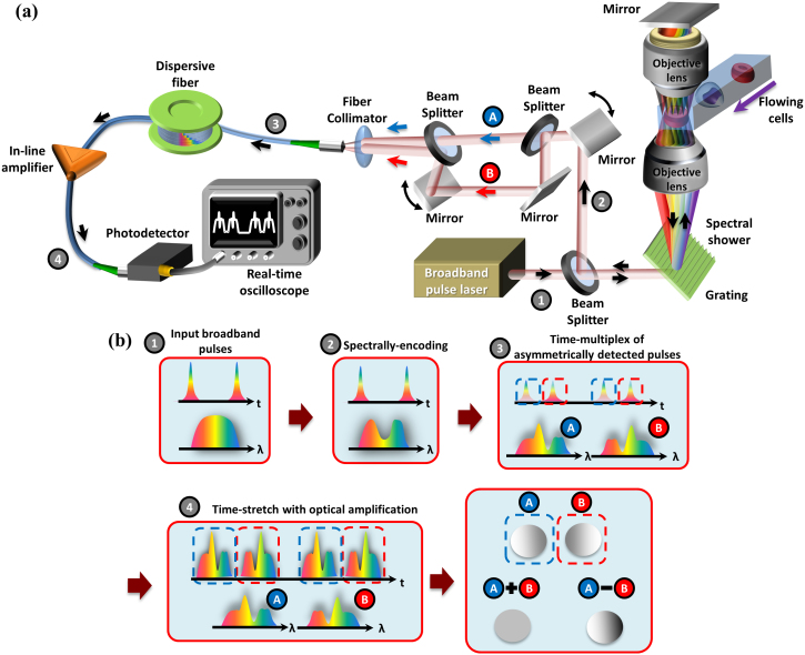
Figure 2. General schematic of an ATOM system.
(a) A broadband light pulsed beam (The temporal pulse train and the corresponding spectrum are shown in box 1 of (b)) is first spatially dispersed by a diffraction grating to generate a 1D spectral shower. It is then focused by an objective lens for illumination such that different wavelengths are focused on different positions on the sample, i.e. the flowing cells in this example. The spectrally-encoded light double-passes the cell through another objective lens and a mirror. The double-passed spectrally-encoded pulses, which are now encoded with the spatial information of the sample, are then restored back to an undispersed pulsed beam by the grating (see box 2 in (b)). They are further split into two different paths (beams A and B) such that the two beams are coupled into the fiber core with the equal angles but opposite orientations. Such off-axis coupling angles of both beams are controlled by the steering mirrors shown in (a). One of the beams is time-delayed so that they are multiplexed in time without temporal overlap. The two time-multiplexed signals reveal opposite phase-gradient contrasts because of the opposite off-axis coupling orientations of beams A and B (see box 3 in (b)). The time-multiplexed signals then undergo the time-stretch process and the in-line optical image amplification to perform wavelength-to-time mapping and to compensate the intrinsic loss in the fiber (see box 4 in (b)). A photodetector and a real-time oscilloscope are used for detecting the signals. Note that the time-stretch signal in each pulse period corresponds to one single-shot line-scan. In each line-scan, two different signals, which have the opposite phase-gradient contrasts (A and B), are obtained simultaneously. The 2D image captured through either beam A or B is named as single-angle ATOM image. By calculating the difference of the two signals (A − B) for each line scan, one can obtain a 2D dual-angle ATOM image with differential (enhanced) phase-gradient contrast. By calculating the sum of the two signals (A + B), one can on the other hand obtain a 2D dual-angle ATOM image with absorption contrast. A homogenous sphere is depicted in (b) as an example.

