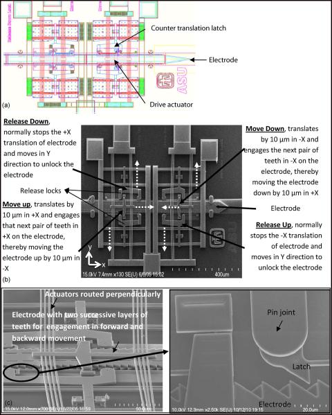
Fig. 1.
(a) Computer-aided design (CAD) diagram of the microelectrode actuated by the Chevron-latch type of actuation mechanism. (b) SEM image of a microelectrode actuated by Chevron-latch mechanism. The microelectrode is capable of bidirectional movement, and a pair of disengage actuators activates the “release down” actuator that frees the microelectrode which is moved down by the “move down” actuator. The microelectrode moves up by a similar mechanism. The broken arrows indicate the direction of displacement of the actuators. (c) SEM image of the Chevron-latch mechanism showing the complex structures of dual countertranslation latches and an overlying layer of bulky drive actuators. Enlarged portion shows two rows of teeth (pointing in opposite directions) realized on successive layers of polysilicon constituting the microelectrode to allow bidirectional movement and the point of contact between the latch and the microelectrode.

