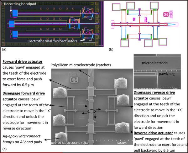
Fig. 2.
(a) CAD diagram of the new generation of MEMS microelectrode device with an array of three microelectrodes actuated by Chevron-peg microactuators. The microelectrodes are electrically connected to the recording bond pad via spring type leads. (b) CAD diagram showing an enlarged image of the microelectrode actuated by the Chevron-peg type of actuation mechanism with a pair of disengage and drive actuators placed opposed to each other. (c) SEM image of microelectrode actuated by Chevron-peg type of actuation. The microelectrode has maximum displacement of 5 mm in steps of about 6.5 μm. The inset shows the encircled region which is the contact between the pawl/peg and a single row of teeth on the microelectrode.

