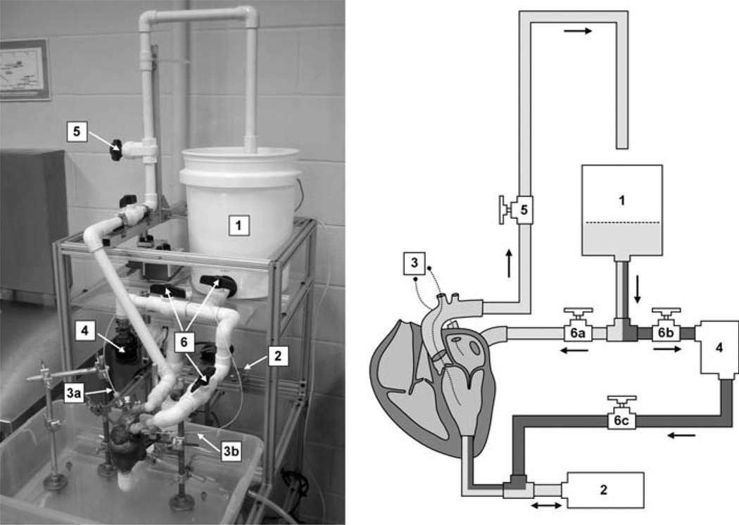
FIGURE 1.
The proposed system. Left: photograph of the system in operation. Right: schematic of system components: atrial filling reservoir (1), PD pump (2), pressure catheters (3), centrifugal pump (4), aortic outflow resistance valve (5), and static pressure mode valves (6). Dynamic and static pressure mode pathways are shaded light and dark, respectively.

