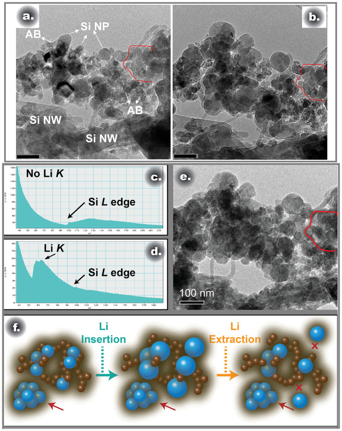
Figure 6.
(a) TEM image of the starting state and (b) final state of lithiation of the conventional composite anode; (c) Li K edge and Si L edge from the region inside and (d) outside the region labeled in red; (e) final delithiated state of the conventional composite anode; (f) schematic drawing showing the structural evolution of the conventional composite anode during the lithium insertion and extraction.

