
Fig. 3.
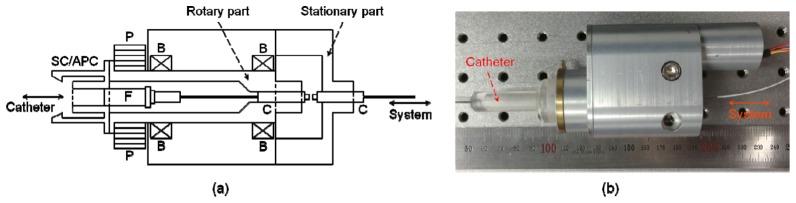
Fiber-optic rotary junction. (a) Schematic diagram of the core optical junction part of the FRJ. P, pulley; F, angle-polished ceramic ferrule; B, bearing; C, fiber-pigtailed collimator. (b) Fiber-optic rotary junction unit assembled and connected to an imaging catheter.