
Figure 2.
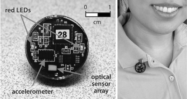
Front view of Daysimeter-D and a subject wearing the device. The optical sensor array and the monolithic accelerometer are indicated along with the two red light emitting diodes used for interfacing this version of the Daysimeter with the docking station (not shown). The coin-cell battery powering the device is on the back-side of the circuit board.