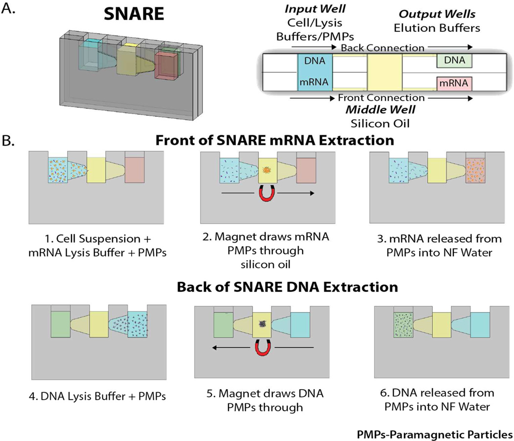
Figure 1.
A) (left) Picture of SNARE device with dimensions labeled and (right) top down schematic of SNARE device with wells labeled. Note the two fluid paths. One on the front of the device and one on the back. mRNA extraction occurs along the front and DNA extraction occurs along the back. B) Operation of SNARE for mRNA and DNA extraction and purification from a single sample. Steps 1–3 show front side of SNARE for mRNA isolation. Steps 4–6 show backside of SNARE for DNA isolation. (PMPs: Paramagnetic Particles)

